Instructions - Parts Stainless Steel Tank Stands 3A0395R EN For supplying material to HFR™ plural-component proportioners. For professional use only. Not approved for use in European explosive atmosphere locations. 100 psi (0.7 MPa, 7.0 bar) Maximum Working Pressure 100 psi (0.7 MPa, 7.0 bar) Maximum Air Pressure Important Safety Instructions Read all warnings and instructions in this manual. Save these instructions. See page 3 for model information.
Contents Models . . . . . . . . . . . . . . . . . . . . . . . . . . . . . . . . . . . 3 Related Manuals . . . . . . . . . . . . . . . . . . . . . . . . . . . 3 Warnings . . . . . . . . . . . . . . . . . . . . . . . . . . . . . . . . . 4 Important Two-Component Material Information . 6 Isocyanate Conditions . . . . . . . . . . . . . . . . . . . . . 6 Material Self-ignition . . . . . . . . . . . . . . . . . . . . . . 6 Keep Components A and B Separate . . . . . . . . . 6 Moisture Sensitivity of Isocyanates .
Models Models The following table lists the tank stand module part numbers and the components included with each. Includes: Part Agitator Slinger Plate Heat Insulation Chiller Desiccant Dryer Level Sensors ✔ ✔ ✔ ✔ ✔ ✔ 46 Liter Tanks 24D562 24D564 24D568 24D569 24D570 24D571 24D572 24D573 24D565 24C317 24D574 24D575 24D576 24D577 24D578 24D579 24P091 ✔ ✔ ✔ ✔ ✔ ✔ ✔ ✔ ✔ ✔ ✔ 75 Liter Tanks ✔ ✔ ✔ ✔ ✔ ✔ ✔ ✔ ✔ ✔ ✔ ✔ ✔ ✔ ✔ ✔ ✔ ✔ ✔ ✔ ✔ 7.
Warnings Warnings The following warnings are for the setup, use, grounding, maintenance, and repair of this equipment. The exclamation point symbol alerts you to a general warning and the hazard symbols refer to procedure-specific risks. When these symbols appear in the body of this manual, refer back to these Warnings. Product-specific hazard symbols and warnings not covered in this section may appear throughout the body of this manual where applicable.
Warnings WARNING WARNING FIRE AND EXPLOSION HAZARD Flammable fumes, such as solvent and paint fumes, in work area can ignite or explode. To help prevent fire and explosion: • • • • Use equipment only in well ventilated area. Eliminate all ignition sources; such as pilot lights, cigarettes, portable electric lamps, and plastic drop cloths (potential static arc). Keep work area free of debris, including solvent, rags and gasoline.
Important Two-Component Material Information Important Two-Component Material Information Isocyanate Conditions Spraying or dispensing materials containing isocyanates creates potentially harmful mists, vapors, and atomized particulates. Read material manufacturer’s warnings and material MSDS to know specific hazards and precautions related to isocyanates. Prevent inhalation of isocyanate mists, vapors, and atomized particulates by providing sufficient ventilation in the work area.
Important Two-Component Material Information Changing Materials • When changing materials, flush the equipment multiple times to ensure it is thoroughly clean. • Always clean the fluid inlet strainers after flushing. • Check with your material manufacturer for chemical compatibility. • Most materials use ISO on the A side, but some use ISO on the B side. • Epoxies often have amines on the B (hardener) side. Polyureas often have amines on the B (resin) side.
Component Identification Component Identification Tank Feed System A B C D H E G F r_24C317_3A0395a_1c FIG.
Component Identification Electrical Panel Components The electrical panel is located on the inside of the tank stand enclosure, and includes the circuit breakers, a fluid control module, and a low power temperature control module. Circuit Breakers CB115 CB130 FIG. 2: Component Identification - Circuit Breakers Ref.
Component Identification Fluid Control Module (FCM) AA AC AH AG ti12337a ti12336a AE AF AD AB FIG. 3: Component Identification - FCM Key: AA AB AC AD Fluid Control Module (FCM) Base Module Connection Screws Access Cover AE AF AG AH Module Status LEDs CAN Connectors Level Sensor Input Fill Solenoid Signal Low Power Temperature Control Module BA BG BD BB BE BC ti12356a BF ti12357a FIG.
Component Identification Heat Zone and Fluid Control Selection The tank feed system supports independent temperature control by utilizing a low power temperature control module. The system also supports fluid control by utilizing an FCM. Both the low power temperature control module and the FCM are located on the electrical panel within the enclosure. NOTE: Tank stands are configured for the A (Red) side. Adjust rotary switch setting if tank is being used on B (Blue) side.
Installation Installation Grounding Products that include heated tanks must be grounded. Grounding reduces the risk of static and electric shock by providing an escape wire for the electrical current due to static build up or in the event of a short circuit. Improper installation of the grounding plug increases the risk of electric shock. Do not modify the plug provided; if it does not fit the outlet, have the proper outlet installed by a qualified electrician.
Installation 9. Route each level sensor (H) wire (J1, J2, J3) through the corresponding well nut (CC). See FIG. 8 for wire location on tank. 13. Being careful to not cross-threads, thread the level sensor well (CA) into the corresponding tank port and lightly tighten with a crescent wrench. CA CB CC Wires J3 J2 CD J1 r_24b969_3A0395a_7a FIG. 8: Tank Ports FIG. 7: Level Sensor Assembly 10.
Installation Install Ultrasonic Level Sensor NOTE: The ultrasonic level sensor is only used on two gallon tanks. Install Chiller (customer supplied) The following instructions apply to tank modules (24C317, 24D562, 24D564, 24D565) that include the heat exchanger assembly (G). NOTE: Graco does not supply the chiller assembly. 1. Turn main power off. 2. Relieve tank air pressure. See Pressure Relief Procedure, page 17. 1. Connect incoming water to inlet heat exchanger port. 2.
Installation Auto-Refill Installation: customer supplied feed system Auto-Refill Installation: Graco supplied feed system NOTE: The auto-refill assembly is not assembled when shipped. NOTE: The auto-refill assembly is not assembled when shipped. 1. Empty tank (C). 1. Empty tank (C). 2. Remove plug from lower, rear of tank. 2. Remove plug from lower, rear of tank. 3. Install auto-refill assembly in 3/4 npt port. 3. Connect feed pump outlet hose to tank. 4.
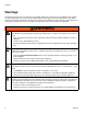
Setup Setup Calibrate Barrel Style Level Sensors 2. Close the shut-off ball valves at the base of the tanks. 3. If the tank lid has a fill port, turn off any systems that might refill the tank during the vacuum de-gas procedure. NOTE: Calibration is not required for ultrasonic style level sensors or high temperature level sensors. 1. Locate the calibration button on the sensor (11) closest to the electrical connector through one of the four holes of the sensor well housing (CA). 2.
Operation Operation See HFR Setup-Operation manual for system operation instructions. Pressure Relief Procedure Startup Start System See HFR Setup-Operation manual for system startup instructions. NOTE: Relieving air pressure in the machine means that the supplied dry air will be replaced by moist air. Do not leave the machine exposed to moist air for more than 30 minutes.
Maintenance Maintenance Replacement Filters Daily Maintenance • • • • • Desiccant Dryer Install Upgrade Tokens Replace silica gel units when the desiccant color or moisture indicator has changed color from Blue (meaning dry) to Pink (meaning wet). NOTE: The Fluid Control Module and Temperature Control Module connection to the system is temporarily disabled during the installation of upgrade tokens. 1. Turn off and depressurize the line containing the dryer unit. To install software upgrades: 2.
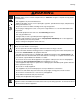
Troubleshooting Troubleshooting Problem No agitation. Cause Agitator motor is not turning. Solution Ensure the system main power is ON. Intermittent electrical connections. Ensure all electrical connections to the motor are secure. See electrical schematic in either the HFR Repair-Parts manual. Check fuse at agitator switch. Check if motor circuit breaker in base cube has tripped. See electrical schematic in either the HFR Repair-Parts manual.
Troubleshooting Problem Material is not heating. Cause Blanket heater not working. Solution Ensure the system main power is ON. Intermittent electrical connections. Material temperature variations. Ensure all electrical connections to the blanket heater are secure. See electrical schematic in either the HFR Repair-Parts manual. FCM errors. Ensure the tank RTD connections are secure. See electrical schematic in either the HFR Repair-Parts manual. Check if FCM circuit breaker has tripped.
Troubleshooting Problem Material is not cooling. Cause Chiller control solenoid not working. Solution Ensure the system main power is ON. Intermittent electrical connections. Material temperature variations. Ensure all electrical connections to the chiller control solenoid are secure. See electrical schematic in either the HFR Repair-Parts manual. FCM errors. Ensure the tank RTD connections are secure. See electrical schematic in either the HFR Repair-Parts manual.
Troubleshooting Problem Level sensor is not sensing material when material is present. Cause Level sensors out of calibration. Solution Ensure the system main power is ON. Level sensors blocked inside tank. Level sensor is sensing material when material is not present. Calibrate level sensor. Intermittent electrical connections. Check inside tank to ensure there is nothing blocking the level sensor. FCM errors. Ensure all electrical connections to the level sensor are secure.
Troubleshooting Problem Tank is not refilling. Cause Air solenoid valve not operating. Solution Check the material supply feed to the tank. Leaking or damaged air lines. Check inside tank to ensure there is nothing blocking the level sensor. Intermittent electrical connections. Level sensors out of calibration. Supply/feed system is off or empty. Ensure the main air to tank connections are secure.
Troubleshooting Problem Tank is overfilling. Cause Solution Level sensors out of calibration. Calibrate level sensors. Level sensors blocked inside tank. Check inside tank to ensure there is nothing blocking the level sensor. Intermittent electrical connections. Ensure the main air to tank connections are secure. Ensure the air lines from the air solenoid valve to the fill valve or feed pump are securely connected and that there are no leaks.
Troubleshooting Problem Cause Solution System is not circulating material. Bypass valve damaged or not operating. Ensure the system main power is ON. Material hoses incorrectly connected. Ensure the main air to tank connections are secure. Material hose leakage. Ensure the air lines from the bypass air solenoid valve to the bypass valve are securely connected and that there are no leaks. Ensure all electrical connections to the bypass air solenoid valve are secure.
Troubleshooting Problem Cause Tank stand module is not communicating with system. Intermittent electrical connections. Solution Ensure the system main power is ON. FCM errors. Ensure power disconnect on base cube is ON. Ensure all power and communication connections from the GMS system to the tank stand are secure. See electrical schematic in either the HFR Repair-Parts manual. Check tank stand circuit breaker in GMS power distribution box to see if it has tripped.
Repair Repair Replace Agitator Fuse Tank Lid Gasket 1. Turn off main power. NOTE: If the tank includes an agitator, use a capable hoist to lift the tank lid and agitator assembly out of the day tank. 2. Slide open the fuse drawer. 3. Remove old fuse and replace with new fuse. Tools/Supplies Required: Fuse Drawer and Fuse • Hoist (if an agitator is installed) • Drop cloth • Crescent wrench • 3 ft. x 3 ft. air tight plastic sheet and removable tape • Screwdriver • Lithium o-ring grease 1.
Repair 6. Lift the tank lid assembly (B) off of the tank and set on the drop cloth. NOTICE Damage to the level sensors may occur when there is an agitator installed and the lid is removed. To avoid damage to level sensors, remove the tank lid assembly while keeping the agitator away from the level sensor assemblies. 7. Use an air tight plastic sheet and removable tape to cover the day tank opening. Tape the sheet in place. 8.
Repair Level Sensor and Well 9. Apply PTFE paste and PTFE tape to the male threads of the level sensor well housing. NOTE: For proper level sensor function, the tip of the level sensor well must protrude at least 1/8 in. into the tank (C). CA 10. Being careful to not cross-threads, thread the level sensor well into the tank (C) and lightly tighten with a crescent wrench. 11.
Electrical Schematics Electrical Schematics Electrical Panel, Tank Stand with Agitator, Heater/Chiller 30 3A0395R
Electrical Schematics Continued 3A0395R 31
Electrical Schematics Continued 32 3A0395R
Electrical Schematics Continued 3A0395R 33
Electrical Schematics Electrical Panel, Tank Stand with Agitator 34 3A0395R
Electrical Schematics Continued 3A0395R 35
Electrical Schematics Continued 36 3A0395R
Parts Parts 38L and 75L Tank Modules 1 Ref. 4 Shown Mounting screws supplied with assembly.
Parts 38L and 75L Tank Modules 1 23 17 (within tank) 16 Mounting screws supplied with assembly.
Parts 38L and 75L Tank Module Parts The following tables on this and the next three pages list the varying part numbers, common part numbers, and quantities by tank module assembly.
Parts Tank Module and Quantity Ref Part Description 24C317 24D562 24D564 24D565 24D568 24D569 24D570 24D571 16 FITTING, assy, bulkhead; 1/4 npt 1 1 1 1 1 1 1 1 17 GUARD, trim, edge 29 29 29 29 29 29 29 29 18 PROBE, assy, recirculation, heat exchange 1 1 1 1 19 24D021 BRACKET, anchor 4 4 4 4 4 4 4 4 20 111800 SCREW, cap, hex head 8 8 8 8 8 8 8 8 22 123398 PLUG, hole; 1.5 in. dia.
Parts 38L and 75L Tank Module Parts (continued) Tank Module and Quantity Ref Part Description 1 ★ TANK, assy, 38L, sst 24D572 24D573 24D574 24D575 24D576 24D577 24D578 24D579 24P091 TANK, assy, 75L, sst ★ TANK, assy, heat, 38L, sst ★ TANK, assy, heat, 75L, sst 2 1 1 1 LID, assy, agitator, vac degas, fill 1 3 ENCLOSURE, frame 1 4 LID, assy, plug, 38L/75L, rim ★ LID, assy, 38L, agitator, rim 1 1 1 1 1 1 1 1 ★ 6 24D852 COVER, assy, tank stand VALVE, assy, ball; 1-1/2 npt, sst
Parts Tank Module and Quantity Ref Part Description 24D572 24D573 24D574 24D575 24D576 24D577 24D578 24D579 24P091 16 FITTING, assy, bulkhead; 1/4 npt 1 1 1 1 1 1 1 1 1 17 GUARD, trim, edge 29 29 29 29 29 29 29 29 29 18 PROBE, assy, recirculation, heat exchange 19 24D021 BRACKET, anchor 4 4 4 4 4 4 4 4 4 20 111800 SCREW, cap, hex head 8 8 8 8 8 8 8 8 8 22 123398 PLUG, hole; 1.5 in. dia.
Parts 2 Gallon Tank Module - 24J243 516 500d 519590 599 526 521 518 520 519 500A 515 598 526 543 508 522 511 518 517 505 597 596 500C 500D 587 591 591 513 536 529 524 533 503 507 536 532 514 583 523 596 534 527 528 530 503 512 500E 500B 518 500F 592 527 583 504 503 501 546 577 553 539 540 541 542 565 566 533 568 595 594 554 593 570 3A0395R ti17775b 43
Parts 2 Gallon Tank Module (continued) 556 553 548 544 569 553 575 578 555 572 573 575 574 571 575 578 567 547 549 550 545 549 551 552 573 561 ti7774a 577 44 562 563 3A0395R
Parts 2 Gal Tank Module (continued) Ref.
Parts Heated Tank Assemblies Ref. 50 38L and 75L Heated Tank Assemblies 51 50 52 Part ✓257762 ◆257772 ✓257757 ◆257758 53 54 ✓257760 ◆257761 257759 256611 55 256558 56 121615 57 121682 58 59 60 61 121599 24D847 124270 261076 51 52 61 54 60 53 Description Qty. TANK, assy. 1 38L, SST 75L; SST INSULATOR, blanket assy. 1 38L 75L BLANKET, assy., heat 1 38L, 240V 75L, 240V SENSOR, thermowell assy., RTD 1 SENSOR, assy.; 1.5 in., RTD, 4-pin 1 m8 SWITCH, assy.
Parts Tank Lid Assemblies Lid with agitator for 38L tanks Lid with agitator for 75L tanks Lid with Agitator 107 109 Ref 101 . 101a . 101b Part 257605 124741 16K267 . 101c . 101d . 101e . 101f . 101g . 101h . 101i . 101j . 101k . 101l . 101m . 101n . 101o . 101p . 101q . 101r . 101s . 101t . 101u 158223 108803 100021 122775 15Y358 15V746 122760 122761 101885 122774 15Y360 122772 15Y357 15Y363 15Y355 105510 112222 100985 15R328 . 101v . 101w . 101x . 101y . 101z . 101aa . 101ab▲ . 101ac . 101ad .
Parts Lid Assembly 154 158 155 148 153 166 162 164 156 165 149 150 151 161 160 152 144 141 157 158 159 142 143 146 141 163 147 r_24B967_3A0395a_1a Ref.
Parts Plug Assembly for Lid Vacuum Degas Lid Assembly 171 185 2 183 172 184 186 182 181 173 r_24B967_3A0395a_1b r_257756_3A0395a_1a Ref. 171 172 173 Part 16A354 15Y363 15Y355 Description PLUG GASKET, mounting NUT Qty. 1 1 1 187 2 Apply thread sealant and PTFE thread tape. Ref. 181 182 183 184 185 186 187 3A0395R Part 15M621 122767 103347 257746 124400 257602 Description LID, agitator BUSHING,; 1/2 x 1/4 npt VALVE, safety; 100 psi KIT, vacuum tree GAUGE, pressure/vac VALVE, assy.
Parts Electrical Panel, 230V for Heat 203 202 236 201 234 237 Ref.
Parts Electrical Panel, 230V for No Heat 203 202 236 234 201 237 Ref.
Parts Electrical Panel, 230V for Heat Parts Electrical Panel, 230V for No Heat Parts Ref. 201 202 203 204★ 205★ 206 207❖ 208 209❖ Part 117644 102556 123352 102410 289697 256270 289696 121597 210 121226 211❖ 24D747 212 213 214 215 216 218 219 220 221 222❖ 223 224 225★ 226 227 228 229 52 124064 114993 102063 113003 100015 112776 123296 123297 123363 123381 121612 100985 123351 100166 24C292 Description Qty.
Parts 3A0395R 53
Parts Electrical Panel, 230V for 2 Gallon Tanks Only 503 519 502 517 518 504 520 521 501 508 509 511 505 507 522 516 525 513 515 524 510 512 506 523 514 ti7778a 54 3A0395R
Parts Ref. 501 502 503 504 505 506 507 508 509 510 511 512 513 514 515 516 517 518 519▲ 520 521 522 523▲ 524 525 Part 24C116 117644 102556 121612 289697 289696 24H240 102063 114993 102598 100985 24C115 112776 123381 100166 121226 121000 124005 16D656 24H241 15U075 100015 196548 277674 24D847 Description Qty.
Parts Heat Exchanger Assembly 266 268 264 255 256 251 266 267 262 252 264 252 257 253 261 254 2 Apply thread sealant and PTFE thread tape to all male npt threads as needed. Ref. 251 252 253 254 256 257 261 262 264 266 267 268 56 r_257968_3A0395Aa_1a Part Description Qty. 123072 EXCHANGER, heat, tank, 0.50 1 plates 123071 COUPLING, pipe; 1 in. npt, ff 2 123073 NIPPLE, hex; 1 in. npt x 3/4 in. npt 1 123028 VALVE, solenoid; 240V 1 123998 ELBOW; 3/4 in. npt x 3/4 in.
Parts Air Dryer Filter 285 284 282 283 281 287 289 290 286 287 291 292 293 r_24C159_3A0395Aa_1a 2 Apply thread sealant and PTFE thread tape to all male npt threads as needed. Ref. 281 282 283 284 285 286 287 288 Part 121019 123377 123379 104984 156971 289 290 291 292 293 295★ 123380 112944 107194 100214 111303 054106 121018 123376 Description Qty.
Parts Ball Valve Assemblies 301 Ball Valve Assembly Ball Valve Assembly with Filter 302 301 304 303 302 305 306 310 311 307 308 309 303 304 305 306 r_257742_3A0395Aa_1a 307 308 309 r_24E107_3A0395Aa_1a 2 Apply thread sealant and PTFE thread tape to all male npt threads as needed. Ref. 301 302 303 304 305 306 307 308 309 309 310 311 58 Part 121136 123001 123003 123000 121135 123002 123348 123349 24E024 24P094 Description Qty. BUSHING, hex; 2 in. npt x 1-1/2 in. npt 1 NIPPLE; 1-1/2 x 6 in.
Parts Recirculation Probe Assembly 2 Apply thread sealant and PTFE thread tape. 326 2 324 2 325 327 2 328 321 322 2 r_24C156_3A0395A_2 Ref. 321 322 324 Part 166466 124280 121478 325 124233 326 327 328 123082 119992 121686 3A0395R Description Qty. FITTING, tee, pipe, female 1 BUSHING; 3/4 npt x 1/4 npt 1 FITTING, compression; 3/16 x 1/4 1 npt SENSOR, RTD, 4 pin; 1kohm, 4.25 1 in.
Parts Transfer Pump Valve, 24C157 331 333 332 333 334 332 r_24C157_3A0395Aa_1b Ref. 331 332 333 334 60 Part 120900 121021 121018 100721 Description VALVE, solenoid, 3 way MUFFLER; 1/4 npt ELBOW, male, swivel; 1/4 npt PLUG, pipe Qty.
Accessories and Kits Accessories and Kits Level Switch Assembly, 24D271 Vacuum Tree Kit, 257746 Third level sensor proximity switch option. Connection kit to add vacuum to the tank. 408 407 410 406 403 401 r_24D271_3A0395Aa_1a 405 402 r_257746_3A0395Aa_1a Ref. 401 402 403 410 Part 16A511 121511 16A512 123394 Description Qty. HOUSING, well, proximity 1 SENSOR, capacitive, 18 mm 1 NUT, well, proximity 1 HARNESS, sensor, level, tank, (3) Ref Ref.
Accessories and Kits Supplied Feed Refill Kit, 257770 High Flow Supplied Feed Refill Kit, 24P673 Refill kit for customer-supplied feed systems. Refill kit for customer-supplied feed systems. 413 415 501 502 503 414 412 504 503 417 504 411 505 416 506 r_257770_3A0395Aa_1b Ref.
Accessories and Kits Insulator Blanket Assembly, 257757 Single Nitrogen Harness 257778 For use with heated 46 liter tanks. Part 15U022 121208▲ Description BLANKET, insulation LABEL, warning TAPE ADHESIVE 421 Qty. 1 1 2 1 424 425 ▲ Replacement Danger and Warning labels, tags, and cards are available at no cost. 422 427 Insulator Blanket Assembly, 257758 426 For use with heated 75 liter tanks. Part 15U023 121208▲ Description BLANKET, insulation LABEL, warning TAPE ADHESIVE Qty.
Accessories and Kits Double Nitrogen Harness 257779 Vacuum Pump Assembly, 257916 431 453 433 452 436 454 455 437, 438 432 435 433 439, 440, 441 436 437 438 441 439 440 Ref. 431 432 433 434 435 436 437 438 439 440 441 r_257916_3A0395Aa_1a 451 r_257779_3A0395Aa_1a Part Description Qty. 122647 REGULATOR, nitrogen; 1/4 npt, 1 1-15 psi 122771 CONNECTOR, Y 1 122649 NUT 2 122654 FERRULE 2 122773 GLAND, spiral, 1/4 in. 2 122758 HOSE, air; 0.25 ID, 0.53 OD, nylon, 20 ft.
Accessories and Kits 3A0395R 65
Dimensions Dimensions Bolt Mounting Pattern and Dimensions D = 24.0 in. (609.6 mm) E = 13.0 in. (330.2 mm) D A E Right Front C r_24C317_3A0395a_1c B A = 83.0 in. (2108 mm); 38L/75L tanks with agitation A = 69.4 in. (1763 mm); 38L/75L tanks without agitation A = 54.0 in. (1372 mm); 7.5L tanks without agitation B = 26.0 in. (661 mm) C = 34.6 in.
Technical Data Technical Data Maximum material working pressure . . . . . . . . . . . . . . . 100 psi (0.7 MPa, 7 bar) Maximum feed supply pressure . . . . . . . . . . . . . . . . . . . 100 psi (0.7 MPa, 7 bar) Maximum air working pressure . . . . . . . . . . . . . . . . . . . 100 psi (0.7 MPa, 7 bar) Maximum fluid working temperature . . . . . . . . . . . . . . . with level sensors 150°F (66°C) without level sensors 190°F (88°C) Line voltage requirements . . . . . . . . . . . . . . . . . . . . .
Graco Standard Warranty Graco warrants all equipment referenced in this document which is manufactured by Graco and bearing its name to be free from defects in material and workmanship on the date of sale to the original purchaser for use. With the exception of any special, extended, or limited warranty published by Graco, Graco will, for a period of twelve months from the date of sale, repair or replace any part of the equipment determined by Graco to be defective.