
User's Manual


Installation
3A0395R 13
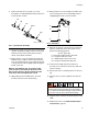
9. Route each level sensor (H) wire (J1, J2, J3)
through the corresponding well nut (CC). See F
IG. 8
for wire location on tank.
10. Measure the length of the level sensor well housing,
and then measure the depth of the hole in the tank
where the well is inserted. Note these measure-
ments as they will be need later.
11. Being careful to not cross-threads, thread assem-
bled level sensor (CB) into well housing until it bot-
toms out against the bottom of the well. The bottom
of the level sensor will be slightly visible through the
bottom of the well.
NOTE: In the following step, do not allow PTFE
paste or tape to cover the tip of the level sensor
well. If paste comes in contact with the tip of the
level sensor well, thoroughly wipe it clean.
12. Apply PTFE paste and PTFE tape to the male
threads of the level sensor well housing.
13. Being careful to not cross-threads, thread the level
sensor well (CA) into the corresponding tank port
and lightly tighten with a crescent wrench.
14. Measure the amount of the level sensor well hous-
ing that is visible beyond the day tank hole, then
perform the following equation:
15. The protrusion length must be at least 1/8 in.
(3.2 mm). If not, remove the level sensor well and
restart at step 10.
16. Rotate level sensor to optimal position for wire rout-
ing.
17. Plug the sensor connector (CD) into the level sen-
sors.
18. Plug the sensor connector into the connector on the
FCM.
19. Calibrate the sensor. See Calibrate Barrel Style
Level Sensors, page 16.
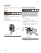
FIG. 7: Level Sensor Assembly
r_24b969_3A0395a_7a
CA
CB
CC
CD
Wires
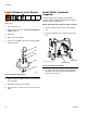
FIG. 8: Tank Ports
Ensure the level sensors are installed in the sensor
well housings before pressurizing the tank. Failing to
do so could cause the well housings to rupture, which
may result in serious injury and material leakage.
J3
J2
J1
P = L1 - (L2 + L3)
P = Protrusion length (inside of day tank)
L1 = Length of level sensor well
L2 = Visible length of level sensor well
L3 = Length of well threads in day tank