Instructions XC Impulse Lubricators 3A0416C EN Uses an external power impulse to control the discharge of grease or oil lubrication to all lubrication points of sliding- and roller bearings, drive- and transport chains, sliding guideways, open gears and seals. For professional use only. Not approved for use in European explosive atmospheres. 75 psi (0.5 MPa, 5 bar) Maximum Working Pressure Important Safety Instructions Read all warnings and instructions in this manual. Save these instructions.
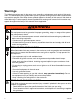
Warnings The following warnings are for the setup, use, grounding, maintenance, and repair of this equipment. The exclamation point symbol alerts you to a general warning and the hazard symbols refer to procedure-specific risks. When these symbols appear in the body of this manual, refer back to these Warnings. Product-specific hazard symbols and warnings not covered in this section may appear throughout the body of this manual where applicable.
WARNING WARNING PRESSURIZED EQUIPMENT HAZARD Fluid from the equipment, leaks, or ruptured components can splash in the eyes or on skin and cause serious injury. Follow the Pressure Relief Procedure before cleaning, checking, or servicing equipment. • Tighten all fluid connections before operating the equipment. • Check hoses, tubes, and couplings daily. Replace worn or damaged parts immediately. • EQUIPMENT MISUSE HAZARD Misuse can cause death or serious injury.
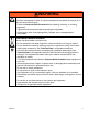
Models WARNING WARNING PERSONAL PROTECTIVE EQUIPMENT You must wear appropriate protective equipment when operating, servicing, or when in the operating area of the equipment to help protect you from serious injury, including eye injury, hearing loss, inhalation of toxic fumes, and burns. This equipment includes but is not limited to: • Protective eyewear, and hearing protection. • Respirators, protective clothing, and gloves as recommended by the fluid and solvent manufacturer.
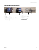
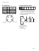
Component Identification Component Identification A B A Plug B Lubrication Canister NOTE: Canister cannot be refilled.
Component Identification Pin Assignment Pressure Relief Procedure Pin Assignment 1 2 3 4 Cable Color Signal brown current + white LED green digital blue current black LED red digital 1. Cover lubrication point (A) and lubricator (B) with a heavy rag to absorb any fluid that may leak out while loosening the adapter. 4 2. Carefully unscrew support adapter (D) from the lubrication point (A).
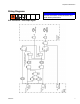
Component Identification Wiring Diagrams NOTICE Incorrect connection of the lubrication unit could destroy electronics.
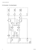
Component Identification PLC Connection - Two Output Signals 8 3A0416C
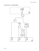
Component Identification PLC Connection - Three Output Signals 3A0416C 9
Installation and Setup Installation and Setup Determining Correct Mounting Method NOTE: • Direct mounting should be used for lubrication points that are easily accessible. • Remote mounting is recommended if you answer YES to any of the questions below. 1. Is the ambient temperature at the lubrication point higher than +50°C (122°F)? 2. Is it necessary to remove protective screens, walls or other types of protection in order to reach the lubrication point? 3.
Installation and Setup A pressure manometer is a simple device that measures pressure output. To build a pressure manometer you need a pressure gage (aa), tee fitting (bb) and stop valve (cc). FIG. 1 shows a correctly assembled pressure manometer, connected to the lubricator and a lubrication point. dd ff bb cc aa ee FIG. 1 aa bb cc dd ee ff Pressure Gauge Tee Fitting Stop Valve Lube Point Lubricator ON / OFF Switch 7. Ensure the stop valve (cc) of the pressure manometer is open. 8.
Installation and Setup Circuit Board Settings Function Display Red and green LED’s (Light Emitting Diodes) are on the circuit board and visible through the transparent cover.
Installation and Setup TABLE 1: Dip Switch Settings / Discharge Amounts in CC / Impulse • Amount of discharge in cc per impulse. • White square indicates position of dip switch. Lubrication Canister Size Dip Switch Position EM-60 3 4 EM-120 3 4 EM-250 3 4 VOL VOL VOL 2.11 2.11 2.11 1.06 1.06 1.06 0.53 0.53 0.53 0.26 0.26 0.26 ON 1 2 TIME ON 1 2 TIME ON 1 2 TIME ON 1 2 TIME NOTE: • As soon as power is supplied, the controller will discharge the set amount once.
Installation and Setup Selecting Mounting Location Installation Guidelines • For all metal to metal connections (i.e., extensions, reducers, etc.) make sure to use LOCTITE® 243* (semi-tight screw locking). *Loctite® is a registered trademark of the Loctite Corporation. • Before installing the lubricator, the lubrication points and any extensions must be adequately pre-lubricated with the same lubricant contained in the lubricator. A 400 gram lubricant cartridge for grease guns is available from Graco.
Installation and Setup Remote Mounting Installations Grease Lubrication with Tube Refer to FIG. 5 - FIG. 7 for examples of correct remote mounting installations. • • Remote installations require a grease line. Graco recommends using a 5/16 inch flexible hose. A Select a position for the lubricator that is easy to access and protected from high-pressure water jets, falling materials, corrosive chemicals and extreme temperatures. B C D E F FIG.
Installation and Setup From-top-lubrication of a Chain with Oil A B C D E F G H J K A Clip, 124086 Support adapter, 124105 Bracket, 124087 Tube connector (User supplied) Nylon tube (User supplied) Tube connections (User supplied) Oil throttle, 124102* L-Bracket, 124098 Bulkhead mounting plate, 124099 Oil brush, 1”x 1.5”, 124090 *The non-return valve (oil throttle (G) should always be placed at the lowest point of the application. B Must be at least 5/16 inch diameter tube.
Installation and Setup Lubrication of Elevated Chain with Oil F E A B C G D FIG. 7 A B C D E F G Clip, 124086 Support adapter, 124105 Bracket, 124087 Tube connector (User supplied) Nylon tube (User supplied) Tube connections (User supplied) Oil throttle, 124102* *The non-return valve (oil throttle: G) should always be placed at the lowest point of the application. Must be at least 5/16 inch diameter tube.
Operation Installing Lubricator to Lubrication Point 7. Install lubricator unit into adapter (B). 1. Clean the lubrication point to remove any potential contaminants. 2. Verify the thread of the lubricator corresponds to the thread of the screw point. 3. Install reducers, extensions, grease line, etc. (if necessary). 4. Verify Dip Switches are correctly set. See Table 1, page 13. 5. Prime the grease line and all accessories with the same grease that is contained in the lubricator.
Changing the Lubrication Canister To begin the discharge: Plug power cable into lubricator (FIG. 8). . Changing the Lubrication Canister When the red and green LED light up at the same time, the lubrication canister is empty and should be replaced. NOTICE FIG. 8 During Operation: • Carry out regular performance checks. Check for possible leakages and the status of the lubricator. • Regularly monitor the fill-level of the transparent lubrication canister.
Changing the Lubrication Canister Installing New Lubrication Canister 1. If a different size lubrication canister or discharge period is going to be used, change dip switches to reflect the new canister size and/or impulse change. See Table 1, page 13. 2. Place drive unit on top of new lubrication canister until the teeth of both pieces are locked. 3. Screw the cover of the drive unit onto the lubrication canister - hand tighten only. 4. Remove plug (A) from bottom of lubrication canister. FIG. 10 9.
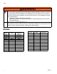
Troubleshooting Troubleshooting Malfunction Possible Cause Wrong cable connection Connect cable according to pin assignment (page 6). Check pin assignment. Break in cable Check voltage at plug. Attach new cable. No power supply Check power supply. Make sure there is sufficient power available for the number of lubricators used. Relay defect in machine Change relays.
Parts Parts Miscellaneous Accessories Replacement Cap Part No. Description Qty. 123951 MOTOR, EM-XC 1 124279 HARNESS, cable, power 1 EM-XP/XC 124086 CLIP 1 124087 BRACKET, plastic 1 124089 BRUSH, pig hair, 1/4 fnpt - 3/4 1 124090 BRUSH, oil, 1 x 1.5 1 124091 BRUSH, oil, 1 x 2.
Technical Data Refill Kits Part No. 24E582 24E583 24E584 24E585 24E586 24E587 24E588 24E589 24E590 24E591 24E592 24E593 Description Qty.
Technical Data Weights and Measurements Type Volume cm3 fl. oz Diameter (D) Length (L) Weight (empty) mm in. mm in. kg lbs EM-60 60 2.03 71 2.8 142 5.60 0.310 0.68 EM-120 120 4.06 71 2.8 165 6.50 0.320 0.7 EM-250 250 8.45 71 2.8 215 8.46 0.360 0.
Notes Notes 3A0416C 25
Graco Standard Warranty Graco warrants all equipment referenced in this document which is manufactured by Graco and bearing its name to be free from defects in material and workmanship on the date of sale to the original purchaser for use. With the exception of any special, extended, or limited warranty published by Graco, Graco will, for a period of twelve months from the date of sale, repair or replace any part of the equipment determined by Graco to be defective.