Instructions EM-XP Time Lubricators 3A0417D Provides a continuous, precise and temperature independent supply of grease or oil lubrication to all lubrication points of sliding- and roller bearings, drive- and transport chains, sliding guideways, open gears and seals. For professional use only. Not approved for use in European explosive atmospheres. 75 psi (0.5 MPa, 5 bar) Maximum Working Pressure Important Safety Instructions Read all warnings and instructions in this manual. Save these instructions.
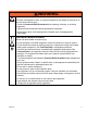
Warnings The following warnings are for the setup, use, grounding, maintenance, and repair of this equipment. The exclamation point symbol alerts you to a general warning and the hazard symbols refer to procedure-specific risks. When these symbols appear in the body of this manual, refer back to these Warnings. Product-specific hazard symbols and warnings not covered in this section may appear throughout the body of this manual where applicable.
WARNING WARNING PRESSURIZED EQUIPMENT HAZARD Fluid from the equipment, leaks, or ruptured components can splash in the eyes or on skin and cause serious injury. Follow the Pressure Relief Procedure before cleaning, checking, or servicing equipment. • Tighten all fluid connections before operating the equipment. • Check hoses, tubes, and couplings daily. Replace worn or damaged parts immediately. • EQUIPMENT MISUSE HAZARD Misuse can cause death or serious injury.
WARNING WARNING PERSONAL PROTECTIVE EQUIPMENT You must wear appropriate protective equipment when operating, servicing, or when in the operating area of the equipment to help protect you from serious injury, including eye injury, hearing loss, inhalation of toxic fumes, and burns. This equipment includes but is not limited to: • Protective eyewear, and hearing protection. • Respirators, protective clothing, and gloves as recommended by the fluid and solvent manufacturer.
Models Models Part No. 24E064 24E063 24E066 24E065 24E069 24E062 24E067 24E068 24E07 2 24E07 1 24E07 4 24E07 3 Volume Output 120C C 120C C 120C C 120C C 120C C 120C C 120C C 120C C 250C C 250C C 250C C 250C C Application Bearing Construction Food Grade H1 Milling Lithium EP1 Lithium EP2 Synthetic Industrial Ultra Spindle Bearing Construction Food Grade H1 Milling Part No.
Component Identification Wiring Diagrams NOTICE Incorrect connection of the lubrication unit could destroy electronics.
Component Identification PLC Connection - Two Output Signals 3A0417D 7
Component Identification PLC Connection - Three Output Signals 8 3A0417D
Installation and Setup Installation and Setup Pin Assignment Pin Assignment 1 2 3 4 Cable Color brown white blue black Determining Correct Mounting Method Signal current + LED green digital current LED red digital • Remote mounting is recommended if you answer YES to any of the questions below. 1. Is the ambient temperature at the lubrication point higher than +50°C (122°F)? 4 2 NOTE: • Direct mounting should be used for lubrication points that are easily accessible. 2.
Installation and Setup Preparing Lubricator for Installation 5. Install lubricator unit into adapter (B). The lubricator has a self-protection mechanism which shuts off the drive unit at counter pressures higher than 5 bar (72.5 psi). Most bearings require 0.5 - 2 bar (7.2 to 29 psi) pressure (without tubes, extensions, angles, etc.). Use the following procedure to check the counter pressure of the application prior to installation.
Installation and Setup 9. Run the manometer for about 20 seconds. Observe the gauge and repeat this procedure until the pressure registered on the gauge stays constant. 10. To determine the counter pressure, wait approximately 5 minutes until the system has relaxed. Do one more discharge by turning the unit OFF; then ON again until it dispenses for no more than 5 seconds. 11. Wait approximately 5 more minutes to make sure the system does not lose pressure and remains constant.
Installation and Setup Circuit Board Settings Function Display Red and green LED’s (Light Emitting Diodes) are on the circuit board and visible through the transparent cover.
Installation and Setup TABLE 1: Dip Switch Settings • • Amount of discharge in cc (1cc = 0.9 gram lubricant) per 100 operating hours. White square indicates position of dip switch. Canister Size Dip Switch Position ON 1 EM-60 3 4 EM-120 3 4 EM-250 3 4 Discharge period VOL VOL VOL 8.33 16.67 34.72 1 month continuous operation 2.78 5.56 11.57 3 months continuous operation 1.39 2.78 5.79 6 months continuous operation 0.69 1.39 2.
Installation and Setup Selecting Mounting Location Installation Guidelines • For all metal to metal connections (i.e., extensions, reducers, etc.) make sure to use LOCTITE® 243* (semi-tight screw locking). *Loctite® is a registered trademark of the Loctite Corpo• Before installing the lubricator, the lubrication points and any extensions must be adequately pre-lubricated with the same lubricant contained in the lubricator. A 400 gram lubricant cartridge for grease guns is available from Graco.
Installation and Setup Remote Mounting Installations Grease Lubrication with Tube Refer to FIG. 5 - FIG. 7 for examples of correct remote mounting installations. A • Remote installations require a grease line. Graco recommends using a 5/16 inch flexible hose. • Select a position for the lubricator that is easy to access and protected from high-pressure water jets, falling materials, corrosive chemicals and extreme temperatures. B C D E F FIG.
Installation and Setup From-top-lubrication of a Chain with Oil A B C D E F G H J K A Clip, 124086 Support adapter, 124105 Bracket, 124087 Tube connector (User supplied) Nylon tube (User supplied) Tube connections (User supplied) Oil throttle, 124102* L-Bracket, 124098 Bulkhead mounting plate, 124099 Oil brush, 1”x 1.5”, 124090 *The non-return valve (oil throttle (G) should always be placed at the lowest point of the application. B Must be at least 5/16 inch diameter tube.
Installation and Setup Lubrication of Elevated Chain with Oil F E A B C G D FIG. 7 A B C D E F G Clip, 124086 Support adapter, 124105 Bracket, 124087 Tube connector (User supplied) Nylon tube (User supplied) Tube connections (User supplied) Oil throttle, 124102* *The non-return valve (oil throttle: G) should always be placed at the lowest point of the application. Must be at least 5/16 inch diameter tube.
Installation and Setup Installing Lubricator to Lubrication Point 8. Screw lubricator to lubrication point, hand tight only. 1. Clean the lubrication point to remove any potential contaminants. NOTICE To ensure optimal lubrication: 2. Verify the thread of the lubricator corresponds to the thread of the screw point. • 3. Install reducers, extensions, grease line, etc. (if necessary). Seal threads of all connecting parts with a suitable, standard sealant.
Operation Operation Before operation verify: • The lubricator does not have any visible damage. • The lubricator canister is filled with the requested grease or oil. • For oil filled lubrication canisters, an oil throttle must be attached. • • • The “VOL” switches 3 and 4 of the 4-way code switch match the correct size of the lubrication canister. The “TIME” switches 1 and 2 of the 4-way code switch in the drive unit match the desired discharge period.
Changing the Lubrication Canister Changing the Lubrication Canister When the red and green LED light up at the same time, the lubrication canister is empty and should be replaced. NOTICE The drive unit and circuit board must always be protected from moisture to prevent damaging these components. Always change the lubrication canister in a dry place. Removing Lubrication Canister Installing New Lubrication Canister 1.
Changing the Lubrication Canister 8. Plug cable back into lubricator (FIG. 10). FIG. 10 9. The control time will start with the corresponding pause time. Lubrication Canister Disposal Dispose of hazardous fluid in approved containers, and according to applicable guidelines. Read the MSDS to know the specific hazards of the fluids you are using. Storage When lubricators are not immediately installed, they must be stored in a dry, dust free, sunlight protected room, indoors.
Troubleshooting Troubleshooting Malfunction Possible Cause Wrong cable connection Connect cable according to pin assignment (page 6). Check pin assignment. Break in cable Check voltage at plug. Attach new cable. No power supply Check power supply. Make sure there is sufficient power available for the number of lubricators used. Relay defect in machine Change relays.
Parts Parts 400 Gram Lubricant Cartridges Miscellaneous Accessories Part No. Description 123950 124086 124087 124089 124090 124091 124092 124093 124100 124101 124102 124109 124113 124114 124115 124116 124119 MOTOR, EM-XP CLIP BRACKET, plastic BRUSH, pig hair, 1/4 fnpt - 3/4 BRUSH, oil, 1 x 1.5 BRUSH, oil, 1 x 2.
Technical Data Technical Data Cable Construction Conductor cross-section dimensions Cable is drag chain qualified, approved for the smallest bending radius 60 mm. 4 x 0.25 mm2 Power Supply 15 - 25 VDC (max 30 VDC) for at least 2 minutes Temperature range -10°C to +50 °C (+14°F to +122°F) Maximum output pressure 5 bar (75 psi) Storage Conditions Dry, dust free Temperature +20°C ± 5°C (+68°F ± 9°F) Air born Noise Emission <70 dB(A)† Loctite® is a registered trademark of the Loctite Corporation.
Technical Data Discharge Amount per Cycle Discharge Amount per Discharge Cycle Discharge Period Pause Time Months h:min cm3 fl. oz. cm3 fl oz. cm3 fl. oz. 1 3 6 12 1:30 4:37 9:17 18:36 0.13 0.004 0.26 0.008 0.53 0.17 EM-60 EM-120 EM-250 Weights and Measurements Type Volume Diameter (D) Length (L) Weight (empty) cm3 fl. oz mm in. mm in. kg lbs EM-60 60 2.03 71 2.8 142 5.60 0.310 0.68 EM-120 120 4.06 71 2.8 165 6.50 0.320 0.7 EM-250 250 8.45 71 2.
Graco Standard Warranty Graco warrants all equipment referenced in this document which is manufactured by Graco and bearing its name to be free from defects in material and workmanship on the date of sale to the original purchaser for use. With the exception of any special, extended, or limited warranty published by Graco, Graco will, for a period of twelve months from the date of sale, repair or replace any part of the equipment determined by Graco to be defective.