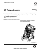
Instructions-Parts XP Proportioners 3A0420T EN Mechanically linked fixed ratio plural-component system used for proportioning, mixing, and spraying two component coatings. For professional use only. Important Safety Instructions Read all warnings and instructions in this manual. Save these instructions. See page 11 for maximum working pressure and model information. XP70 system shown with hoppers and optional solvent flush pump and heaters.
Contents Related Manuals . . . . . . . . . . . . . . . . . . . . . . . . . . . 3 Warnings . . . . . . . . . . . . . . . . . . . . . . . . . . . . . . . . . 4 Important Two-Component Material Information . 7 Isocyanate Conditions . . . . . . . . . . . . . . . . . . . . . 7 Material Self-ignition . . . . . . . . . . . . . . . . . . . . . . 7 Keep Components A and B Separate . . . . . . . . . 7 Moisture Sensitivity of Isocyanates . . . . . . . . . . . 7 Foam Resins with 245 fa Blowing Agents . . . . . .
Related Manuals Related Manuals Manuals are available at www.graco.com.
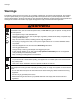
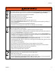
Warnings Warnings The following warnings are for the setup, use, grounding, maintenance, and repair of this equipment. The exclamation point symbol alerts you to a general warning and the hazard symbols refer to procedure-specific risks. When these symbols appear in the body of this manual, refer back to these Warnings. Product-specific hazard symbols and warnings not covered in this section may appear throughout the body of this manual where applicable.
Warnings WARNING WARNING SKIN INJECTION HAZARD High-pressure fluid from gun, hose leaks, or ruptured components will pierce skin. This may look like just a cut, but it is a serious injury that can result in amputation. Get immediate surgical treatment. • Do not spray without tip guard and trigger guard installed. • Engage trigger lock when not spraying. • Do not point gun at anyone or at any part of the body. • Do not put your hand over the spray tip.
Warnings WARNING WARNING TOXIC FLUID OR FUMES HAZARD Toxic fluids or fumes can cause serious injury or death if splashed in the eyes or on skin, inhaled, or swallowed. • Read MSDSs to know the specific hazards of the fluids you are using. • Store hazardous fluid in approved containers, and dispose of it according to applicable guidelines. • Always wear chemically impermeable gloves when spraying, dispensing, or cleaning equipment.
Important Two-Component Material Information Important Two-Component Material Information Isocyanate Conditions Spraying or dispensing materials containing isocyanates creates potentially harmful mists, vapors, and atomized particulates. Read material manufacturer’s warnings and material MSDS to know specific hazards and precautions related to isocyanates. Prevent inhalation of isocyanate mists, vapors, and atomized particulates by providing sufficient ventilation in the work area.
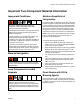
Important Two-Component Material Information Changing Materials • Changing material types used in your system requires special attention to avoid equipment damage and downtime. • Always clean the fluid inlet strainers after flushing. • When changing between epoxies and urethanes or polyureas, disassemble and clean all fluid components and changes hose sets. • Check with your material manufacturer for chemical compatibility. • Most materials use ISO on the A side, but some use ISO on the B side.
Overview Overview Usage The XP is a mechanically linked fixed ratio system that can mix and spray most two-component epoxy and urethane protective coatings. When using quick-setting material (less than 10 minute pot life) a remote mix manifold must be used or materials must mix at the gun. Quickset manifold 24M398 is recommended for quick-setting material.
Initial System Setup Initial System Setup 1. Check the shipment for accuracy. Ensure you have received everything you ordered. See Component Identification, page 14. 2. Check for loose fittings and fasteners. 3. Install optional solvent flush pump kit 262393, if ordered. See manual 310863 for instructions. 4. Mount and connect optional heaters, if ordered. See the heater adapter kit manual 406861 for instructions and the heater manual 309524. 5.
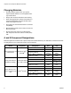
Models Models The XP systems are approved for use in hazardous locations only if the base model, all accessories, all kits, and all wiring meet local, state, and national codes. Cart-Mounted Systems NOTE: All cart-mounted systems listed are Ex rated: II 2 G c IIA T2 See Accessories and Kits on page 55 for a list of all optional accessories. NOTE: The “Standard” mix manifold selection means the mix manifold is mounted on the cart and comes with mixers, 25 ft of 3/8 in. mix hose, and 10 ft of 1/4 in.
Models XP70 with NXT 6500 Air Motor XP50 with 6500 Air Motor Typ e 12 Pump Model Package 282000 --282101 282102 282100 282105 282106 282151 282152 282150 282155 282156 282201 282202 282200 282205 282206 282251 282252 282250 282255 282256 282301 282302 282300 282305 282306 282331 282330 282332 282401 282402 282400 282405 282406 283101 282100 283102 283201 282200 283202 283301 282300 283302 283401 282400 283402 571000 --571101 571100 571102 571151 571150 571152 571201 571200 571202 571251 571250 571252 5
Models Bare Proportioning Pump Packages Packages include motor, pump lowers, and all connection hardware. NOTE: All pump packages are Ex rated except for the XP-h pump packages (284xxx): II 2 G c IIA T2 Building systems with bare proportioning pump packages: • Over Pressure Protection must be used, see page 9. See chart on page 39 to identify the over pressure relief valves to use with your system. • All components must meet or exceed maximum working pressures.
Component Identification Component Identification E X M B G R A Mounting Components for Pump Package H U N F P V A T B S J C D D D Y K W L r_571101_3a0420a_1a-2 FIG.
Component Identification Fluid Control Assembly Standard Mix Manifold shown AA AH AC AM AF AE Key: AA AB AC AD AE AF AG AH AJ AK AL AM AJ AN Fluid Manifold Mix Manifold Circulation Handle Solvent Flush Valve Dual Shutoff Handle Fluid Pressure Gauges Fluid Supply Inlet (Behind Fluid Manifold) Fluid Circulation Fittings B Component Adjustable Fluid Restrictor; see page 27 A and B Mix Manifold Check Valves Solvent Inlet Check Valve Automatic, Spring Loaded, Color-Coded Over Pressure Relief Valves; with
Component Identification 45:1 Solvent Flush Pump Kit 262393 (optional) Pump Key: BA BD BA BB BD BE BF BG Solvent flush pump (Merkur Pump) Fluid Inlet Muffler Prime/Flush/Sample valve Fluid Outlet Hose Circulation hose BF BE BG BB (suction hose not shown) r_571100_3a0420a_4a-2 FIG. 4 Air Controls Key: DC DA DB DC DD DE DE Solvent Pump Air Shutoff Valve (Relieving) Solvent Pump Air Pressure Regulator Solvent Pump Air Pressure Gauge Air Outlet Air Inlet DB DA DD r_571101_3a0420a_5a-2 FIG.
Component Identification Air Line • Bleed-type master air valve (CA): Required in your system to relieve air trapped between it and the air motor when the valve is closed. Be sure the valve is easily accessible from the pump and located downstream from the air regulator. Trapped air can cause the pump to cycle unexpectedly, which could result in serious injury from splashing or moving parts. • • Pump air regulator (CB): Controls pump speed and outlet pressure.
Setup Setup Location Pump: use ground wire and clamp (supplied). Loosen grounding lug locknut (W) and washer (X). Insert ground wire end (Y) into lug (Z) slot and tighten locknut securely. Connect ground clamp to a true earth ground. Y The XP35, XP50, and XP70 systems are approved for use in hazardous locations only if the base model, all accessories, all kits, and all wiring meet local, state, and national codes. 1. Locate the proportioner on a level surface. 2.
Setup Wire Systems with Explosion-Proof Heaters (Hazardous location systems only) If your system is rated for hazardous areas, and you have explosion-proof heaters, you must have a qualified electrician connect heater wiring. Ensure wiring and installation comply with local electrical codes for hazardous areas. Improperly installed or connected equipment will create a hazardous condition and cause fire, explosion, or electric shock. Follow local regulations.
Setup Motor Position The motor position must be set for the volume mix ratio of the system. 3. Place wrench on adapter rod (104) then use supplied tool to loosen the serrated yoke nut (V) above the yoke (T). Air Motor shown 104 NOTE: Changing the motor position does not change the mix ratio. V T Check Motor Position r_571101_3a0420a_2a-2 1. Verify that the correct pumps are mounted for your mix ratio by volume. See chart in Bare Proportioning Pump Packages on page 13. 4.
Setup Connect Air Supply 1. Connect the air supply hose to the 3/4 npt(f) air filter inlet (C). NOTE: Use a 3/4 in. (19.1 mm) ID minimum air hose. Air consumption is 75 cfm per gallon per minute spraying. Do not use pin fitting type quick disconnects. Connect Fluid Hose Bundles (Remote Mix Manifold Only) Connect additional fluid hoses to the fluid manifold (AA) when the mix manifold (AB) is remote. Hoses must be properly sized and balanced for your mix ratio. See mix manifold manual for details. 1.
Pressure Relief Procedure Pressure Relief Procedure 8. Engage the trigger lock. Follow Flush Mixed Material, page 28 when you stop spraying or dispensing; and before cleaning, checking, servicing, or transporting equipment. 9. Close the dual shutoff handle (AE) and open the circulation handle (AC). AC AE Relieve A and B Fluid Pressure 1. Engage the trigger lock. r_571101_3A0420A_9a-2 10. Always flush the mix hose after relieving A and B fluid pressure through the mix manifold.
Prime Empty System Prime Empty System Prime A and B Fluids 3. Move the recirculation lines (U) to empty containers. Wear gloves when using flush solvents and/or if the fluid temperature exceeds 110°F (43°C). U NOTE: The equipment is tested with mineral oil at the factory. If necessary, flush out the oil with a compatible solvent before spraying. See Empty and Flush Entire System (new system or end of job), page 29. Do not install the gun spray tip yet.
Prime Empty System Prime Solvent Flush Pump 6. Ensure the trigger lock is engaged. Remove the spray tip. Follow instructions if the optional solvent flush pump kit is used. TI1949a 1. Connect the flush pail ground wire to a metal pail of solvent. 2. Place the siphon tube and the solvent circulation hose (BG) in the pail of solvent. BG 4) ! TI1948a 7. Disengage the trigger lock and trigger the gun into a grounded pail. Use a pail lid with a hole to dispense through.
Prime Empty System Recirculate Prior to Spraying or Re-Prime After a Pump Runs Dry NOTE: Agitate, recirculate, and heat the material only as necessary to avoid mixing air into the fluid. 5. Turn down the air pressure regulator (CB) and then open the main air shutoff valve (CA). Use the air pressure regulator to slowly increase the air pressure to the pumps until they start running slowly. CB Use the recirculation mode when heating the material is required.
Spray Spray 5. Engage the trigger lock. Install the tip on the gun. Wear gloves when using flush solvents and/or if fluid temperature exceeds 110°F (43°C). NOTE: After the first day of spraying follow Pressure Relief Procedure, page 22, and tighten the throat packing nuts on both pumps. 1. If heaters are used, turn them on. To adjust the heater temperature, refer to the Viscon HP manual for instructions, and the Heat Fluid section, page 25. Circulate as necessary. TI1949a 6.
B Side Mix Manifold Restriction B Side Mix Manifold Restriction The B side restrictor (AJ) controls “lead/lag” ratio errors of the A and B flow into the static mixer tubes. These errors occur momentarily when the gun opens. The error is caused by differences in viscosity, volume, and hose expansion. The restrictor is used primarily when the mix manifold is positioned remote from the machine with a short mix hose to the spray gun. It can also be used in the ratio check procedure.
Flush Mixed Material Flush Mixed Material 4. Open the solvent flush valve (AD). AB Flush the mix manifold when any of the following situations occur. • • • breaks in spraying overnight shutdown mixed material in system approaching end of potlife To flush the entire system, see Empty and Flush Entire System (new system or end of job), page 29. Flush Mix Manifold, Hose, and Spray Gun AD 5. Disengage the trigger lock and trigger gun into a grounded pail. Use a pail lid with a hole to dispense through.
Empty and Flush Entire System (new system or end of job) Empty and Flush Entire System (new system or end of job) 2. Engage the trigger lock. Turn the main pump air regulator (CB) fully counter-clockwise to shut off. NOTE: • • TI1949a Cover fluid containers and use the lowest possible pressure when flushing to avoid splashing. • Before color change or shutdown for storage, circulate the solvent at a higher flow rate and for a longer time. Change the solvent when it gets dirty.
Shutdown 7. Run the pumps until the A and B hoppers (J) are empty. Salvage the material in separate, clean containers. 8. Close the main air shutoff valve (CA). 14. Close the dual shutoff handle (AE). 15. Remove pump fluid filters, if installed, and soak in solvent. Clean and replace the filter cap. Always replace the filter o-rings. NOTE: • Fill the A and B pump packing nuts with TSL. Also, always leave some type of fluid, such as solvent or oil, in the system to prevent scale build up.
System Verification System Verification Graco recommends running the following tests daily. Check for Normal Operation NOTE: Spots that take longer to cure indicate insufficient pump loading, leakage, or lead/lag errors at a remote mix manifold. Every time you start spraying: Appearance Test • Watch the fluid gauges (AF). A pressure drop occurs during pump stroke changeover. It should be quick and synchronous. Spray material onto foil.
Maintenance Maintenance Hose Electrical Resistance Check electrical resistance of hoses regularly. If total resistance to ground exceeds 29 megohms, replace hose immediately. Filters 6. Shutdown the sprayer and turn off all power. See Shutdown, page 30. 7. Clean the external surfaces only using a rag soaked in solvent that is compatible with the spray material and surfaces being cleaned. 8. Allow enough time for the solvent to dry before using the system.
Troubleshooting Troubleshooting ✖ Fluid ratio will be wrong. ◆ Purge all air from system before proportioning fluids. Problem System stops or will not start. Cause Solution Air pressure or volume too low. Increase; check air compressor. Closed or restricted air line or air valve. Open or clean. Fluid valves closed. Open. Clogged fluid hose. Replace. Air motor worn or damaged. Repair air motor; see 311238. Displacement pump stuck. Repair pump; see 311762. System speeds up or runs erratically.
Troubleshooting Problem Cause Fluid outlet pressure gauges split only at the top changeover (if one gauge drops the other will rise). Solution Not fully loading one side on upstroke. Increase feed pressure on side that dropped. Increase feed hose size. Clean inlet strainer or hopper screen. Air mixed in fluid from excessive agi- Flush and add new fluid. tation or circulation. Pump Troubleshooting This chart uses proportioning fluid gauges to determine pump malfunctions.
Repair Repair 4. Remove the spring clamp (130) and coupling (119 or 120). To avoid serious injury due to the pump assembly falling, secure a hoist to the lift ring. Follow Shutdown procedure on page 30, which includes flushing, if service time may exceed pot life time, before servicing fluid components, and before transporting system to a service area.
Repair Remove Motor 1. Stop the pumps near the bottom of their stroke. Follow Shutdown, page 30. 2. Disconnect the air line from the air motor (103). 9. Follow the steps in reverse order to reinstall the air motor. NOTE: Position air motor for correct mix ratio. See Motor Position on page 20 for instructions. Torque nuts (108) to 50-60 ft-lb (68-81 N•m). 3. Remove the air motor rod cover (121) and pump guards (122). Air Motor shown 8. Refer to the air motor manual to service or repair the air motor.
Repair 201 206 203 209 214 207 216 206 Air Flow 214 215 208 213 204 Air Flow 202 211 205 209 210 5, 8 r_571101_3A0420A_1a-2 FIG.
Repair Mix Manifold Assembly 1 1. Follow Pressure Relief Procedure, page 22. 35 2. Disconnect the fluid hose (25) and the flush hose from the mix manifold (36). 37 3. Loosen the union fittings (306) that connect to the mix manifold adapter fittings. 4. Remove the mix manifold assembly (36). 5. See mix manifold manual for service and repair instructions. 306 r_571101_3a0420a_39a FIG. 11: Fluid Circulation Manifold Replace Over Pressure Relief Valves 1.
Repair 7. Slide handle (311) onto valve stem and rotate approximately 90° until you feel it fully lock against the valve seat. Repeat for opposite side. 12. Install two screws (313) in handles (311). 8. Remove handle then place handle (311) on valve stem (302) at the vertical, or near vertical, position. 14. Operate the handle in and out of the spray and circulate positions. 9. Apply blue threadlock on the nut (304) threads and tighten the handle against the spring (320) and clip (318).
Repair Hoppers Optional Solvent Pump 1. If material is in the hopper pump out the remaining material. 1. Follow Pressure Relief Procedure, page 22. 2. Disconnect the fluid line and air lines from the solvent pump. 2. If the pump has failed: a. Place a waste container beneath the plug on fitting (61). Remove the plug. b. Drain all material from hopper into the waste container. 1 Install plug after material is no longer draining from fitting (61). r_571101_3a0420a_41a c. 3.
Repair Optional Fluid Heaters NOTE: Wiring for heaters is not provided. See the Viscon HP heater manual for wiring, repair, and parts information for explosion-proof heaters. Service and Repair 1. Follow Pressure Relief Procedure, page 22. 2. Disconnect the fluid lines and electrical wiring from the fluid heater. 3. Refer to the Viscon HP heater manual to service or repair. Refer to the heater adapter kit manual 406861 for installation instructions. 4. Reconnect the fluid lines and electrical wiring.
Parts Parts Cart-Mounted System 15 38 1. Apply anaerobic pipe sealant to all non-swiveling pipe threads.
Parts Cart-Mounted System Continued 18 Standard Mix Manifold Models 5 41 35 4 37 22 36 24 48 32 27, 28 23 32 22 27, 28 52 24 27, 28 30 31 24 5 6 25 26 r_571101_3a0420a_44a-1 29 r_571101_3a0420a_45a 18 49 “A” 49 “B” 56 90 59 55 62 58 60 1 69 57 61 89 70 51 66 3A0420T 65 (inside hopper) TI17434a 43
Parts Cart-Mounted System Continued 35 Quickset Mix Manifold Models 36 30 31 TI19233a 44 3A0420T
Parts Parts Common to All Systems Ref Part 1 2 3 6 7 8 9 10 258913 262476 111841 100101 113362 154628 113436 124410 11 124664 12 13 14 15 16 17 19 21 24 15A913 191824 113807 258982 101242 258983 16F206 111218 H75003 37 38 47 49 50 53 54 58 59 67 69 70▲ 106212 116139 206995 15U654 555357 124259 124291 116704 15V421 16E336 16F615 16F359 71 89 91 16F536 16G819 126786 Description Qty 1 CART, weldment 1 AXLE 2 WASHER, plain 5/8 4 SCREW, cap, hex head 2 WHEEL, semi-pneumatic 2 WASHER 2 RING, retaini
Parts Parts Varying By Model - XP35 Systems Ref Part 4 281100 281200 262803 281300 281400 24M422 5 100133 18 100131 20 512519 22 158491 23 15M987 25 H43825 26 15B729 27 262478 28 248927 29 150287 30 H42510 31 XTR504 32 162024 35 262784 36 262807 41 158683 48 101566 51 124450 52 124293 55 24E872 56 262479 57 262480 60 H52506 H52510 61 16D376 62 111192 64 103347 113498 114055 16M190 65 262482 66▲ 15T468 68 114958 90 16J688 Description PUMP PACKAGE, fixed ratio, 1.0:1 PUMP PACKAGE, fixed ratio, 2.
Parts Parts Varying By Model - 282xxx (XP50) Systems Ref Part 4 282100 282150 282200 282250 282300 282330 282400 24M423 5 100133 18 100131 20 512519 22 158491 23 15M987 25 H53825 26 15B729 27 262478 28 248927 29 150287 31 XTR504 32 162024 35 262783 36 262807 41 158683 48 101566 51 124450 52 124293 55 24E872 56 262479 57 262480 60 H52506 H52510 61 62 64 16D376 111192 103347 113498 114055 65 262482 66▲ 15T468 68 114958 90 16J688 282000 282101 282102 282105 282106 282151 282152 282155 282156 282201 282202
Parts Parts Varying By Model - 283xxx (XP50 Quickset) Systems 10 1 3 1 10 1 11 7 4 2 1 1 1 1 1 2 2 2 1 1 2 1 2 4 1 2 2 10 1 1 7 3 4 2 1 1 1 1 1 2 11 7 4 2 1 1 1 1 1 2 2 2 1 1 2 1 2 4 1 2 2 10 1 3 1 10 1 283402 1 7 3 4 2 1 1 1 1 1 2 1 283401 3 11 7 4 2 1 1 1 1 1 2 2 2 1 1 2 1 2 4 1 2 2 10 1 1 283302 7 3 4 2 1 1 1 1 1 2 1 283301 1 283202 1 283201 Description PUMP PACKAGE, fixed ratio, 1.0:1 PUMP PACKAGE, fixed ratio, 2.0:1 PUMP PACKAGE, fixed ratio, 3.
Parts Parts Varying By Model - XP70 Systems 1 7 3 3 4 2 1 1 3 1 1 1 1 2 1 1 2 2 1 2 1 10 1 7 11 7 3 7 3 3 3 3 4 4 4 2 2 2 1 1 1 1 1 1 3 3 3 1 1 1 1 1 1 1 1 1 1 1 1 2 2 2 1 1 1 1 1 1 2 2 2 2 2 2 2 1 1 1 2 1 1 2 2 2 2 4 1 1 1 2 2 10 10 10 1 1 1 11 7 3 4 2 1 1 3 1 1 1 1 2 1 1 2 2 2 1 2 1 1 2 2 4 1 571402 1 571401 1 571302 1 571301 1 571252 1 571251 1 571202 1 571201 1 571152 1 571151 571102 Description PUMP PACKAGE, fixed ratio, 1.0:1 PUMP PACKAGE, fixed ratio, 1.
Parts Bare Proportioning Pump Package Model 571100 shown 123 122 137 101 136 103 138 129 3 128 2 3 122 109 3 102 1 110 7 6 7 1 106 104 121 1 133 105 4 101 134 135 139 107 108 111 113 1 5 140 131 116 117 112 119 117 or 118 116 130 120 130 1 108 r_258914_3A0420A_3a r_258914_3A0420A_2a 50 1 Torque together to 50-60 ft-lb (68-81 N•m). 2 Torque to 145-155 ft-lb (196-210 N•m). 3 Apply blue thread sealant.
Parts Parts Common to All Pump Packages Ref 101 105 106 107 108 109 110 111 112 113 Part 262465 262468 262469 154636 101712 16D451 262470 262471 15H392 262472 Description PLATE, motor ROD, tie, 14.25 long, with shoulder ROD, tie, 14.25 long, 1.
Parts Air Controls, 258983 201 206 203 209 214 2 207 206 Air Flow 216 214 215 208 211 213 204 Air Flow 202 211 205 209 210 TI17433a r_571100_3A0420A_1a-1 1. Apply anaerobic pipe sealant to all non-swiveling pipe threads. 2 Connect hose (214) to fitting (206) and air distribution manifold (213). Ref. No. Part No.
Parts Fluid Circulation Manifold with Over Pressure Relief Valve Assembly 262784 (XP35); 262783 (XP50); 262806 (XP70) 312 313 309 308 311 308 318 6 3 304 320 309 5 303 308 310 2 3 4 313 302 305 320 317 5 318 301 311 317 305 307 302 304 2 3 4 3 6 316 r_258988_3a0420a_1c 1. Ref 301 302† Apply anaerobic pipe sealant to all non-swiveling pipe threads. 2 Torque to 28-32 ft-lb (38-43 N•m). 3 Apply blue anaerobic adhesive to threads.
Recommended Spare Parts Recommended Spare Parts Keep these spare parts on hand to reduce downtime. Pump Repair Kits See page 13 to see what pumps are used on your system. See lower manual for repair kits.
Accessories and Kits Accessories and Kits Acceptable For Use in Explosive Atmospheres 20 Gallon Hopper Kit, 255963 Blue 7 Gallon Hopper Kit, 24F376 Green 7 Gallon Hopper Kit, 24F377 1-1/2 in. ID Hose Flex Feed Kit, 262820 Mount to the sides of the XP system. See manual 406860 for more information. XP Wall Mount Bracket, 262812 Solvent Pump Kit, 262393 Floor Stand for 20 Gal. Hopper, 262824 Works with air or hydraulic XP systems. Leg Stand, 24M281 For supplying solvent to the mix manifold.
Accessories and Kits Not Approved For Explosive Atmospheres These kits do not carry the EX mark. 2:1 Feed Pump Kit, 256275 For supplying viscous materials from a drum to XP system. See manual 312769 for more information. 2:1 Drum Feed Kit, 256232 One T2 pump feed kit and one Twistork agitator kit for mixing and supplying viscous materials from a 55 gallon drum to XP system. See manual 312769 for more information.
Technical Data Technical Data XP Proportioners Maximum Fluid Working Pressure Maximum Air/Hydraulic Oil Working Pressure Combined Fluid Output (cc/cycle) Pressure Ratio Fluid Flow at 40 cpm Hydraulic Fluid Consumption (XP-h models only) Air inlet size Maximum air pressure supply to the system Fluid pump inlets without hoppers Fluid gauge manifold outlets Fluid mix manifold inlets Mix manifold material outlet Maximum feed pressure from remote source Sound pressure Sound power Maximum Storage Time Maximum Li
Dimensions Weight: Full XP35, XP50, or XP70 System with heaters, solvent flush pump, and hoppers Bare XP35, XP50, or XP70 system with no heaters, solvent flush pump, or hoppers XP35, XP50, or XP70 Pump only XP-h System 575 lb 261 kg 425 lb 193 kg 286 lb 290 lb 130 kg 132 kg Dimensions Top View Bare System Full System 35 in. (889 mm) 32 in. (813 mm) 52 in. (1321 mm) r_571100_3a0420_100a Side View 60 in.
Dimensions Floor Mounting Dimensions, Top View 32 in. (812.8 mm) 22 in. (558.8 mm) 6.75 in. (171.45 mm) 16.90 in. (429.26 mm) 15.25 in. (387.35 mm) 40 in.
Dimensions Bare Proportioner Mounting Hole Dimensions The dimensions below is the minimum opening size for mounting a bare proportioner. 10.125 in. (257.175 mm) 5.06 in. (128.52 mm) 3/8-16 (4x) 120° (4x) 10.375 in. (263.525 mm) 2.25 in. (57.15 mm) 150° (4x) 4.05 in. (102.87 mm) 9.25 in. (234.95 mm) 0.25 in. (6.35 mm) 3.75 in. (95.25 mm) 7.5 in. (190.5 mm) 14.35 in. (364.
Dimensions Wall Mount Bracket 262812 Dimensions 15.0 in. (381 mm) 11.8 in. (300 mm) 9.75 in. (248 mm) 18.4 in. (467 mm) 17.9 in.
Dimensions Floor Stand 24M281 Dimensions 21.2 in. (538 mm) 17.8 in. (451 mm) 32.7 in. (829 mm) 30.3 in. (770 mm) ti19047a Hydraulic Unit Dimensions Shown installed on floor stand 53 in. (1346 mm) ti19048a 30.3 in. (770 mm) 62 17.8 in.
Dimensions 3A0420T 63
Graco Standard Warranty Graco warrants all equipment referenced in this document which is manufactured by Graco and bearing its name to be free from defects in material and workmanship on the date of sale to the original purchaser for use. With the exception of any special, extended, or limited warranty published by Graco, Graco will, for a period of twelve months from the date of sale, repair or replace any part of the equipment determined by Graco to be defective.