Instructions - Parts List High-Flo® 4-Ball Pumps 3A0538F EN Air-powered pumps for low pressure, high volume circulation of finishing materials. Do not use for flushing or purging lines with caustics, acids, abrasive line strippers, and other similar fluids. For professional use only. Important Safety Instructions Read all warnings and instructions in this manual. Save these instructions. See page 3 for model information, including maximum working pressure.
Contents Models . . . . . . . . . . . . . . . . . . . . . . . . . . . . . . . . . . . 3 Related Manuals . . . . . . . . . . . . . . . . . . . . . . . . . . . 3 Warnings . . . . . . . . . . . . . . . . . . . . . . . . . . . . . . . . . 4 Installation . . . . . . . . . . . . . . . . . . . . . . . . . . . . . . . . 6 Grounding . . . . . . . . . . . . . . . . . . . . . . . . . . . . . . 6 Stand Mount . . . . . . . . . . . . . . . . . . . . . . . . . . . . 7 Wall Mount . . . . . . . . . . . . . . . . . . . . . .
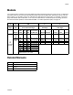
Models Models Your model number is marked on the pump identification plate located toward the rear of the air motor. To determine the model number of your pump from the following matrix, select the six digits which describe your pump. The first digit is always J for circulation pumps. The remaining five digits define the construction. For example, a circulation pump with stainless steel construction, a 3.
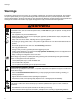
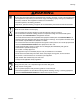
Warnings Warnings The following warnings are for the setup, use, grounding, maintenance, and repair of this equipment. The exclamation point symbol alerts you to a general warning and the hazard symbols refer to procedure-specific risks. When these symbols appear in the body of this manual, refer back to these Warnings. Product-specific hazard symbols and warnings not covered in this section may appear throughout the body of this manual where applicable.
Warnings WARNING WARNING PERSONAL PROTECTIVE EQUIPMENT You must wear appropriate protective equipment when operating, servicing, or when in the operating area of the equipment to help protect you from serious injury, including eye injury, hearing loss, inhalation of toxic fumes, and burns. This equipment includes but is not limited to: • Protective eyewear, and hearing protection. • Respirators, protective clothing, and gloves as recommended by the fluid and solvent manufacturer.
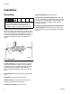
Installation Installation Grounding Object being sprayed: follow local code. The equipment must be grounded. Grounding reduces the risk of static and electric shock by providing an escape wire for the electrical current due to static build up or in the event of a short circuit. Pump: use a ground wire and clamp. See FIG. 1. Remove the green ground screw (Z) from the bottom of the air motor. Insert the screw through the loop on the end of the ground wire (Y) and reattach the screw to the air motor.
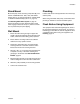
Installation Stand Mount Plumbing Mount the pump in the accessory pump stand (B). Use Part No. 253692 Stand for 1000, 1500, and 2000cc Pumps (see FIG. 2, page 9) and Part No. 218742 Stand for 3000 and 4000cc Pumps (see FIG. 3, page 10). Install a fluid shutoff valve (D) between the mix tank (A) and the pump. See Mounting Stand Hole Layouts on page 24. Secure the stand to the floor with M19 (5/8 in.) bolts which engage at least 152 mm (6 in.) into the concrete floor to prevent the pump from tipping.
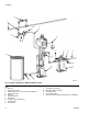
Installation Accessories Install the following accessories in the order shown in FIG. 2 and FIG. 3, using adapters as necessary. NOTE: Accessory Air Control Kits are available for the NXT Air Motor. The kits include a master air valve, air regulator, and filter. Order the kit separately. See manual 311239 for more information. Air Line Fluid Line See FIG. 2 and FIG. 3. • Fluid filter: with a 60 mesh (250 micron) stainless steel element to filter particles from the fluid as it leaves the pump.
Installation H J J M P Y K L B D G D E A N N F D C TI15598a FIG. 2. Typical Installation for 1000, 1500, and 2000cc Pumps Key: A B C D E F G H J K L Mix Tank 253692 Pump Stand Fluid Supply Line; 1-1/2 in.
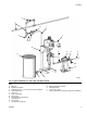
Installation H J M J P Y K L D G D E A N N B D F C TI15607a FIG. 3. Typical Installation for 3000 and 4000cc Pumps Key: A B C D E F G H J K 10 Mix Tank 218742 Pump Stand Fluid Supply Line; 2 in.
Operation Operation Pressure Relief Procedure 1. Close the bleed-type master air valve (M). 2. Open the dispensing valve, if used. 3. Open all fluid drain valves (N) in the system, having a waste container ready to catch drainage. Leave drain valve(s) open until you are ready to pump again. Prime the Pump 1. Fill the TSL reservoir to the Maximum fill line with Throat Seal Liquid (TSL). See FIG. 4 on page 13. NOTE: During operation the TSL level in the reservoir will fluctuate slightly at pump changeover.
Maintenance Maintenance Preventive Maintenance Schedule The operating conditions of your particular system determine how often maintenance is required. Establish a preventive maintenance schedule by recording when and what kind of maintenance is needed, and then determine a regular schedule for checking your system.
Maintenance Changing the TSL To change the TSL: Check the condition of the TSL and the level in the reservoir every week, minimum. TSL should be changed at least every month. 1. Shut off the pump. Part No. 206995 Throat Seal Liquid (TSL) carries residue from the pump rod into the reservoir. Discoloration of the TSL fluid is to be expected during normal operation. After some time the TSL will thicken and darken, and must be replaced.
Maintenance 14 3A0538F
Troubleshooting Troubleshooting Problem Pump output low on both strokes. Pump output low on only one stroke. Cause Solution Restricted air supply lines. Clear any obstructions; be sure all shutoff valves are open; increase pressure, but do not exceed maximum working pressure. Exhausted fluid supply. Refill and reprime pump. Clogged fluid outlet line, valves, etc. Clear. Worn piston packing. Replace. See lower manual. Held open or worn ball check valves. Check and repair. Worn piston packings.
Repair Repair Disassembly Reassembly NOTE: The 3000 and 4000cc pumps are easiest to repair when left in the Part No. 218742 accessory pump stand and disassembled as instructed in the lower manual. For repair at a remote location, have another pump stand available. NOTE: If the coupling adapter (105) and tie rods (106) have been disassembled from the motor, see Reassemble the Coupling Adapter and Tie Rods to the Motor on page 17. 1. See FIG. 6. Assemble the coupling nut (103) to the piston rod (R). 2.
Repair Table 1: Coupler Torque Values 101 108 105 1 104 103 1 106 122 R Pump Part No.
Parts Parts High-Flo Pumps with 1000cc, 1500cc, or 2000cc 4-Ball Lowers Common Parts Ref. No. Description 101 MOTOR, NXT, see manual 311238 101 102 108 105 104 103 106 122 107 102 TI15595a 18 103 104 105 106 107 108 122 Part No. see tables, pages 18-19 LOWER, 4-Ball, see manual 3A0539 see tables, pages 18-19 NUT, coupling 184059 COLLAR, coupling 184128 ADAPTER, coupling 15H369 TIE ROD, 14.25 in.
Parts 3.0:1 Ratio, 1500cc Pumps Pump (see page 3) JC30L1 JC30M1 JS30L1 JS30L2 JS30L5 JS30L6 JS30M1 JS30M2 JS30M5 JS30M6 JS30R1 JS30R2 JS30R5 JS30R6 JS30S1 JS30S2 JS30S5 JS30S6 Pump Series A A B B B B B B B B B B B B B B B B 4.
Parts High-Flo Pumps with 3000cc or 4000 cc 4-Ball Lowers Common Parts Ref. No. Description 101 MOTOR, NXT, see manual 311238 101 102 LOWER, 4-Ball, see manual 3A0540 103 104 105 106 108 105 NUT, coupling COLLAR, coupling ADAPTER, coupling TIE ROD, 19.307 in. (490.398 mm) between shoulders 107 NUT, lock, hex; 5/8-11 108 COVER, moisture 122 SHIELD KIT; includes 2 shields Part No. see tables, pages 21-21 see tables, pages 21-21 186925 184129 15H370 15H600 102216 247362 24F254 Qty.
Parts 1.7:1 Ratio, 4000cc Pumps Pump (see page 3) JC17L1 JC17M1 JS17L1 JS17L2 JS17M1 JS17M2 JS17R1 JS17R2 JS17S1 JS17S2 Pump Series A A A A A A A A A A 3.3:1 Ratio, 4000cc Pumps 101 102 NXT Air Motor (see 311238) N34LN0 N34LT0 N34LN0 N34LN0 N34LT0 N34LT0 N34RN0 N34RN0 N34RT0 N34RT0 4-Ball Lower (see 3A0540) 24F453 24F453 24F451 24F452 24F451 24F452 24F451 24F452 24F451 24F452 2.
Dimensions Dimensions High-Flo 1000, 1500, and 2000cc Pumps High-Flo 3000 and 4000cc Pumps A A B C B C TI15596a TI15605a Model JX40XX JX30XX JX20XX JX45XX JX35XX JX23XX JX17XX JX44XX JX33XX 22 Motor NXT2200 NXT2200 NXT2200 NXT3400 NXT3400 NXT3400 NXT3400 NXT6500 NXT6500 Lower Size 1000cc 1500cc 2000cc 1500cc 2000cc 3000cc 4000cc 3000cc 4000cc A in. (mm) B in. (mm) C in. (mm) 45.6 (1158) 28.78 (731) 17.4 (442) 51.4 (1306) 35.5 (901) 23.0 (584) Approx. Weight lb (kg) 94 (42.6) 95 (43.
Motor Mounting Hole Diagrams Motor Mounting Hole Diagrams NXT Model 2200 Four 3/8-16 Mounting Holes NOTE: Adapter Plate 247312 is required to mount an NXT 2200 air motor to the 255143 Wall Bracket. Order separately. 247312 Three 5/8-11 Tie Rod Holes, 5.906 in. (150 mm) x 120° Bolt Circle 3.938 in. (100 mm) 6.750 in. (172 mm) TI8071A TI8841A NXT Model 3400 Four 3/8-16 Mounting Holes 6.186 in. (157 mm) Six 5/8-11 Tie Rod Holes, 8.000 in. (203 mm) x 120° Bolt Circle 5.906 in.
Mounting Stand Hole Layouts Mounting Stand Hole Layouts 253692 Floor Stand (for 1000, 1500, and 2000cc Pumps) 218742 Floor Stand (for 3000 and 4000cc Pumps) 17.0 in. (431.8 mm) 6.41 in. (160 mm) 6.41 in. (160 mm) 30° 19.88 in. (505.0 mm) 16.88 in. (428.8 mm) 30° 60° 11.1 in. (278 mm) 7.4 in. (185 mm) radius 14.50 in. (368.3 mm) TI15859a 24 Threaded 0.68 in.
5143 Wall Mount Bracket 255143 Wall Mount Bracket 17.8 in. (450.9 mm) 14.5 in. (368.3 mm) 2.0 in. (50.8 mm) 5.4 in. (136.5 mm) 7.4 in. (187.3 mm) 5.3 in. (133.4 mm) 1.0 in. (25.4 mm) 9.0 in. (228.6 mm) 1.6 in. (41.4 mm) 12.4 in. (314.3 mm) 7/16 in. (11 mm) diameter holes for mounting to wall 1/2 in. (12.
Technical Data Technical Data Model JX17XX JX20XX JX23XX JX30XX JX33XX JX35XX JX40XX JX44XX JX45XX Maximum Maximum Working Pressure Air Input Pressure psi (MPa, bar) psi (MPa, bar) 170 (1.2, 12.0) 200 (1.4, 14.0) 230 (1.6, 16.0) 300 (2.1, 21.0) 330 (2.3, 23.0) 350 (2.4, 24.0) 400 (2.8, 28.0) 440 (3.0, 30.0) 450 (3.1, 31.0) 100 (0.7, 7.0) Air Consumption See Performance Charts Maximum Fluid Flow at Fluid 60 cycles per Temperature minute Output Rating gpm (lpm) per Cycle (cc) °F (°C) 63 (238.6) 31.
Performance Charts Performance Charts Fluid Outlet Pressure - Black Curves Air Consumption - Gray Curves To find Fluid Outlet Pressure (psi/MPa/bar) at a specific fluid flow (gpm/lpm) and operating air pressure (psi/MPa/bar): To find Pump Air Consumption (scfm or m3/min.) at a specific fluid flow (gpm/lpm) and air pressure (psi/MPa/bar): 1. Locate desired flow along bottom of chart. 1. Locate desired flow along bottom of chart. 2.
Performance Charts NOTE: See Models on page 3 for your pump part number. Key: A 100 psi (0.7 MPa, 7.0 bar) air pressure B 70 psi (0.49 MPa, 4.9 bar) air pressure C 40 psi (0.28 MPa, 2.8 bar) air pressure NOTE: The shaded area within the table shows the recommended range for continuous duty circulation applications. NXT 3400 Air Motor, 2000cc Lower (JX35XX) CYCLES PER MIN. 5 15 10 20 24 28 500 (3.5, 35) 350 (2.4, 24) 70 (1.96) 300 (2.1, 21) A 400 (2.8, 28) 300 (2.1, 21) 50 (1.4) B 250 (1.
Performance Charts NOTE: See Models on page 3 for your pump part number. Key: A 100 psi (0.7 MPa, 7.0 bar) air pressure B 70 psi (0.49 MPa, 4.9 bar) air pressure C 40 psi (0.28 MPa, 2.8 bar) air pressure NXT 6500 Air Motor, 3000cc Lower (JX44XX) psi (MPa, bar) 450 (3.10, 31.0) 200 A 400 (2.75, 27.5) 180 A 160 350 (2.41, 24.1) Fluid Pressure B 120 250 (1.72, 17.2) 100 200 (1.37, 137) C 80 C 150 (1.03, 10.3) Air Flow (scfm) 140 B 300 (2.06, 20.6) 60 100 (0.68, 68) 40 50 (0.34, 3.
Graco Standard Warranty Graco warrants all equipment referenced in this document which is manufactured by Graco and bearing its name to be free from defects in material and workmanship on the date of sale to the original purchaser for use. With the exception of any special, extended, or limited warranty published by Graco, Graco will, for a period of twelve months from the date of sale, repair or replace any part of the equipment determined by Graco to be defective.