
User's Manual


Repair
12 3A0539L
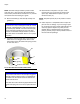
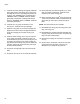
NOTE: One inlet seat (6) includes a pressure relief
valve. See F
IG. 3. This seat must be located exactly
where shown (the left side as viewed in F
IG. 4). Use the
text cast into the inlet housing as a guide.
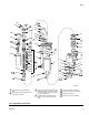
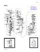
16. Remove the balls (5), inlet seats (6 and 33), and
gaskets (7).
17. Inspect the pressure relief valve in the seat (6) to
make sure it is not clogged. Press down on the
valve's ball to see if the ball and the spring are free
to move. See F
IG. 3.
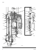
18. Place the flats of the piston nut (12) in a vise.
Unscrew the rod (17) from the nut. Remove the
spacer (44). Disassemble the piston (10) and
remove the seal (11).
NOTE: The piston spacer (44) is not present on 750cc
lowers.
19. Clean all parts in a compatible solvent. Inspect all
parts for wear or damage. If you are using a repair
kit, use all the new parts in the kit, discarding the old
ones they replace. Replace any other parts as
needed. Worn or damaged parts may cause the
pump to perform poorly or cause premature wear of
the new seals and packings.
NOTICE
Be careful not to drop or damage the balls (5) or seats
(6 and 33). A damaged ball or seat cannot seal prop-
erly and the pump will leak. One inlet valve seat (33)
can be reversed to provide longer use of the seat.
However, the fluid inlet seat (6) contains a pressure
relief valve and is not reversible. See F
IG. 3 for proper
orientation.
F
IG. 3. Inlet Seat with Pressure Relief Valve
NOTICE
If the pressure relief valve in the seat (6) is clogged or
filled with material, soak the seat in a compatible sol-
vent. Make sure all material residue is cleaned from
the ball and seat area.
If the relief valve cannot be thoroughly cleaned so that
the ball and spring are free to move, replace the seat
(6).
TI8407a
7
6
ball
spring
pressure relief valve
pin