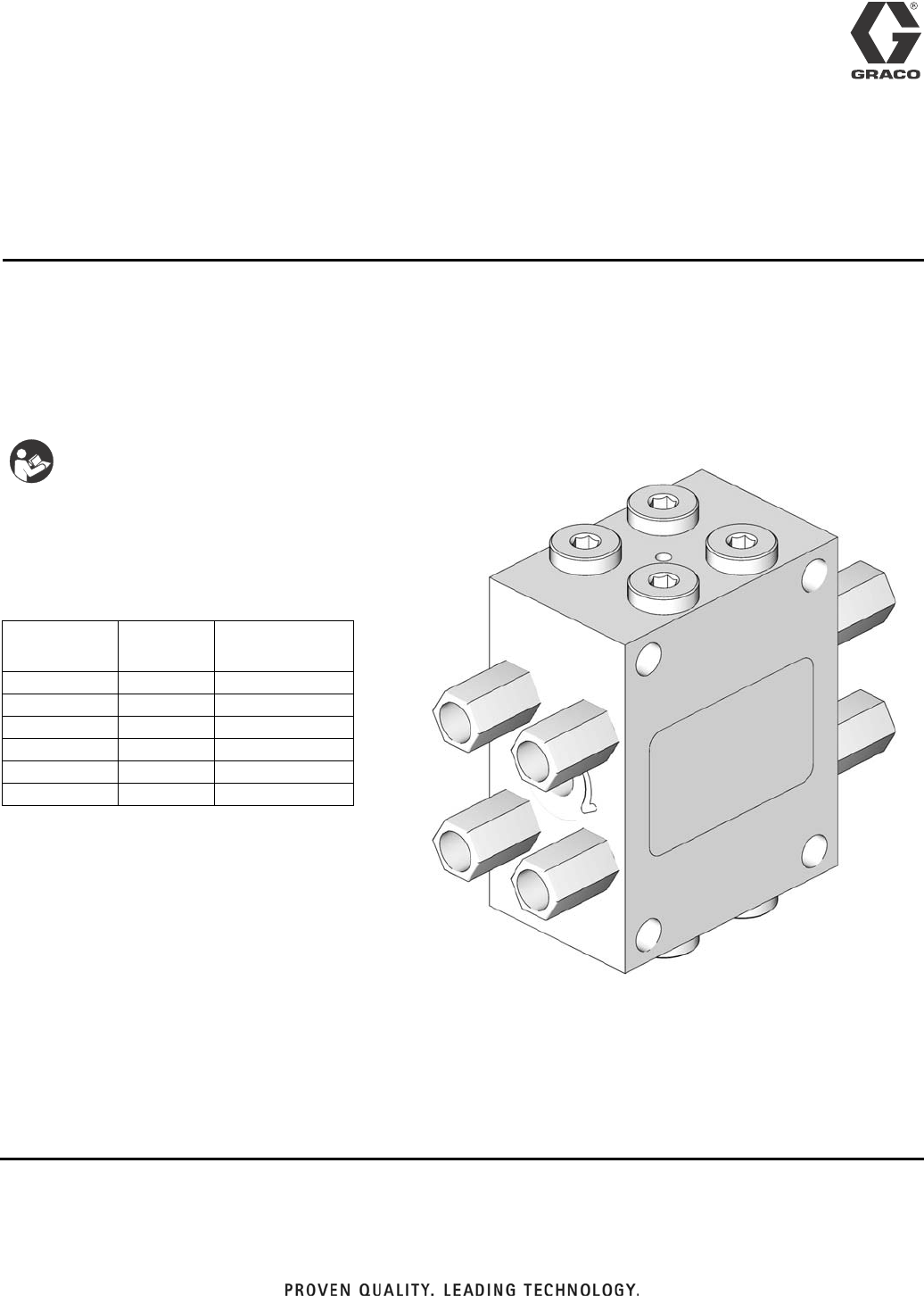
Instructions USP Valve 3A0860F EN Uniblock Series Progressive Valve for oil and grease lubrication. 5076 psi (35 MPa, 350 bar) Maximum Working Pressure Important Safety Instructions Read all warnings and instructions in this manual. Save these instructions. Models For all models: • Discharge per outlet = 0.012 in 3 Model No. 24E406 24E407 24E408 24E409 24E410 24E411 No.
Warnings Warnings The following warnings are for the setup, use, grounding, maintenance, and repair of this equipment. The exclamation point symbol alerts you to a general warning and the hazard symbols refer to procedure-specific risks. When these symbols appear in the body of this manual, refer back to these Warnings. Product-specific hazard symbols and warnings not covered in this section may appear throughout the body of this manual where applicable.
Installation Installation The USP Valve should be ready to install in your system. It has been factory-tested and should not require any additional modification. As long as lubricant is supplied under pressure, the valve will continue to operate . Whenever lubricant flow ceases, the valve pistons stop. When flow resumes, it will start again at the same point in the discharge cycle.
Installation Purging Air from Pump to USP Valve Lines Steps 1- 3, refer to FIG. 3. 1. Install the line from the system pump to the USP valve. Do not completely tighten the connection at the valve’s lube inlet. 2. Cycle the system pump until air-free lubricant is observed flowing from the line at the valve’s lube inlet. 3. Tighten the fitting at the lube inlet port while lubricant is still flowing. The system is now ready for operation. ti13745 FIG.
Installation Blockages Blocks require a higher than normal pumping pressure. Depending on the application or system design, this blockage will usually result in a complete loss of lubricant flow into the total system and no bearing will be receiving lubrication. The loss of flow due to a blockage is first indicated with the higher than normal system pressure that is developed by the pump as it attempts to overcome this blockage.
Parts Parts * FN Part No.
Technical Data Technical Data Wetted Parts Steel, Fluorocarbon Maximum Pressure 5076 psi (35 MPa, 350 bar) Maximum Operating Temperature Fluorocarbon seals 350°F (177°C) Lubricant Oil or grease up to NLGI #2 Output Volume 0.012 in3 Inlet Threads 1/8 - 27 NPT Outlet Adapter Threads 1/8 - 27 NPSF Maximum Cycle Rate with Prox Switch 200 cpm Mounting Holes Accomodate Bolt Diameter 0.25 in.
Technical Data Outlet Pattern Numbering NOTE: • Port combinations do not continue across factory plugged outlets. Factory plugged ports are included on 6, 10 and 14 outlet USP Valve models. On the following diagrams the factory plugged outlets are represented as blacked ports. • Do not remove plugs from the factory plugged outlets.
Notes Notes 3A0860F 9
Graco Standard Warranty Graco warrants all equipment referenced in this document which is manufactured by Graco and bearing its name to be free from defects in material and workmanship on the date of sale to the original purchaser for use. With the exception of any special, extended, or limited warranty published by Graco, Graco will, for a period of twelve months from the date of sale, repair or replace any part of the equipment determined by Graco to be defective.