Operation ® ProMix 2KE 3A0868G EN Pump-Based Plural Component Proportioner Self-contained, electronic two-component paint proportioner. For professional use only. Important Safety Instructions Read all warnings and instructions in this manual. Save these instructions. See pages 3-4 for model information, including maximum working pressure and approvals.
Contents Models . . . . . . . . . . . . . . . . . . . . . . . . . . . . . . . . . . . 3 Warnings . . . . . . . . . . . . . . . . . . . . . . . . . . . . . . . . . 5 Important Two-Component Material Information . 8 Isocyanate Conditions . . . . . . . . . . . . . . . . . . . . . 8 Material Self-ignition . . . . . . . . . . . . . . . . . . . . . . 8 Keep Components A and B Separate . . . . . . . . . 8 Moisture Sensitivity of Isocyanates . . . . . . . . . . . 8 Changing Materials . . . . . . . . . . . . . . . .
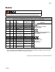
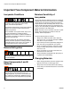
Models Models ProMix 2KE systems are not approved for use in hazardous locations unless the base model, all accessories, all kits, and all wiring meet local, state, and national codes. Approved for Hazardous Location Class 1, Div 1, Group D (North America); Class 1, Zones 1 and 2 (Europe) Part No.
Models Models (continued) Approved for Non-Hazardous Location Maximum Working Pressure USB psi (MPa, bar) Port Part No. Series 24F088 A 3:1 Merkur, A and B 300 (2.1, 21) 24F089 A 23:1 Merkur, A and B 2300 (15.8, 158) 24F090 A 30:1 Merkur, A and B 3000 (20.6, 206) 24F091 A 45:1 Merkur, A and B 4500 (31.
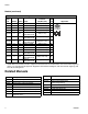
Warnings Warnings The following warnings are for the setup, use, grounding, maintenance, and repair of this equipment. The exclamation point symbol alerts you to a general warning and the hazard symbols refer to procedure-specific risks. When these symbols appear in the body of this manual, refer back to these Warnings. Product-specific hazard symbols and warnings not covered in this section may appear throughout the body of this manual where applicable.
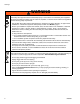
Warnings WARNING INTRINSIC SAFETY Intrinsically safe equipment that is installed improperly or connected to non-intrinsically safe equipment will create a hazardous condition and can cause fire, explosion, or electric shock. Follow local regulations and the following safety requirements. • Only models with model numbers 24F102-24F115, utilizing the air-driven alternator, are approved for installation in a Hazardous (explosive atmosphere) Location. See Models, page 3.
Warnings WARNING EQUIPMENT MISUSE HAZARD Misuse can cause death or serious injury. • Do not operate the unit when fatigued or under the influence of drugs or alcohol. • Do not exceed the maximum working pressure or temperature rating of the lowest rated system component. See Technical Data in all equipment manuals. • Use fluids and solvents that are compatible with equipment wetted parts. See Technical Data in all equipment manuals. Read fluid and solvent manufacturer’s warnings.
Important Two-Component Material Information Important Two-Component Material Information Isocyanate Conditions Spraying or dispensing materials containing isocyanates creates potentially harmful mists, vapors, and atomized particulates. Read material manufacturer’s warnings and material MSDS to know specific hazards and precautions related to isocyanates. Prevent inhalation of isocyanate mists, vapors, and atomized particulates by providing sufficient ventilation in the work area.
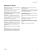
Glossary of Terms Glossary of Terms Dose Size - the amount of resin (A) and catalyst (B) that is dispensed into an integrator. Potlife Time - the amount of time before a material becomes unsprayable. Dose Time Alarm - the amount of time that is allowed for a dose to occur before an alarm occurs. Potlife Volume - the amount of material that is required to move through the mix manifold, hose, and applicator before the potlife timer is reset. Dynamic Dosing - Component A dispenses constantly.
Overview Overview Usage The ProMix 2KE is an electronic two-component paint proportioner. It can blend most two-component paints. It is not for use with quick-setting paints (those with a pot life of less than 5 minutes). • Has dynamic dosing capabilities. It dispenses material A, monitors fluid flow, and dispenses material B in doses to cause the mixture to stay on ratio. • Can proportion at ratios from 0.1:1 to 30.0:1. • Will display the last 50 errors with date, time, and event.
Installation Intrinsically Safe Installation Requirements 1. The installation must meet the requirements of the National Electric Code, NFPA 70, Article 504 Resp., Article 505, and ANSI/ISA 12.06.01. Do not substitute or modify system components as this may impair intrinsic safety. For installation, maintenance, or operation instructions, read instruction manuals. Do not install equipment approved only for non-hazardous location in a hazardous location.
Installation Non-Hazardous Locations 10' CAN CABLE 50' OPTION USB MODULE POWER SUPPLY 20" CAN CABLE LINE POWER FILTER USER INTERFACE MODULE FLUID CONTROL MODULE CAN CABLE LINEAR SENSOR/ REED SWITCH CABLE LINEAR SENSOR/ REED SWITCH CABLE "A" REED SWITCH "B" REED SWITCH "A" LINEAR SENSOR "B" LINEAR SENSOR "A" PRESSURE TRANSDUCER "B" PRESSURE TRANSDUCER FIG. 2.
Installation Display Module Air Supply 1. Use the screws provided to mount the bracket for the Display Module on the front of the Control Box or on the wall, as you prefer. Requirements 2. Snap the Display Module into the bracket. • Compressed air supply pressure: 75-100 psi (517-700 kPa, 5.2-7 bar). • Air hoses: use grounded hoses that are correctly sized for your system. ti16672a 3. Connect one end of the CAN cable (provided) to J6 on the Display Module (either port).
Installation Air Connections Fluid Supply See the System Pneumatic Schematic on page 66 (hazardous location) or page 67 (non-hazardous location). Requirements 1. Tighten all ProMix 2KE system air and fluid line connections as they may have loosened during shipment. • Do not exceed the pressure rating of the lowest rated component. See the identification label. 2. Connect the main air supply line to the main air inlet. This air line supplies the solenoids, valves, and pumps. See FIG. 3.
Installation Component Inlet Remove plug; recirculation outlet. Solvent inlet ti16755a ti16754a SVB SVA DVB DVA PB PA ti15697a MM Key: PA Component A Pump DVA Component A Dose Valve SVA Solvent Valve A PB DVB SVB MM Component B Pump Component B Dose Valve Solvent Valve B Mix Manifold FIG. 5.
Installation Tubing Chart and Diagrams Type Color Air Air Air Air Air Air Air Air Air Air Air Fluid Fluid Fluid Fluid Air Air * Description Green Green Green Green Red Red Red Red Natural Natural Natural ------------Natural Black Starting Point Ending Point Solvent Valve A On Dose Valve A On Solvent Valve B On Dose Valve B On Solvent Valve A Off Dose Valve A Off Solvent Valve B Off Dose Valve B Off Solenoid Air Air Regulator to Pump B Air Regulator to Pump A Pump B to Valve Stack B Pump A to Valve S
Installation GFB1-A ATOM-1 ATOM-2 A2 A3 A Side B Side A1 A3 ti16772a 2G 4G 4R 2R 1R 3R 3G 1G A4 A5 A Side B Side ti16765a A5 A4 A6 A7 ti16766a See Manual 312784 for full setup instructions for a gun flush box.
Installation Electrical Power Connection (non-IS units only) All electrical wiring must be completed by a qualified electrician and comply with all local codes and regulations. Line Enclose all cables routed in the spray booth and high traffic areas in conduit to prevent damage from paint, solvent, and traffic. The ProMix 2KE operates with 85-250 VAC, 50/60 Hz input power, with a maximum of 2 amp current draw. The power supply circuit must be protected with a 15 amp maximum circuit breaker.
Installation Grounding Air and Fluid Hoses Use grounded hoses only. The equipment must be grounded. Grounding reduces the risk of static and electric shock by providing an escape wire for the electrical current due to static build up or in the event of a short circuit. Connect the ProMix 2KE ground wire to the ground screw. Connect the clamp to a true earth ground. If wall power is used to power controls, ground electrical connection according to local codes.
Installation Key: 1 Control Box ground screw 2 Control Box ground wire 3 Pump B ground screw 10 4 Pump B ground wire 1 5 Pump A ground screw 6 Pump A ground wire 7 Gun Flush Box ground screw 8 Gun Flush Box ground wire 9 True Earth Ground - check your local code for requirements. 2 10 Power cable, Display Module/Control Box 3 4 5 6 9 7 8 ti16467a FIG. 9.
Display Module Display Module Screen number Error code Potlife state Ratio Active recipe Operation mode; see page 22 for key LCD display Potlife timers Navigation keys Flow rate Enter key Soft keys Navigation keys Error Reset key Standby key Setup key FIG. 10. Display Module Display Shows graphical and text information related to setup and spray operations. The screen backlight is factory set to remain on.
Display Module Icon Key The following tables present a printable version of the information on the ProMix 2KE icon card. See Table 3, page 52, for a printable version of the error code information on the reverse side of the card.
Display Module Screen Summary NOTE: This summary is a one-page guide to the ProMix 2KE screens, followed by screen maps. For operating instructions, see Basic Operation, page 29. For further detail on individual screens, see Run Mode Details, page 39, or Setup Mode Details, page 42. Run Mode The run mode has three screen sections that control the mixing operations. Mix (Screens 2-4, 38) • Spray (Screen 2) controls most mixing operations. • Batch (Screen 3) controls dispense of a set volume.
Display Module Ranges for User Inputs This table is a one-sheet reference of the data range/options accepted for each user input and the default setting. See the page indicated in the table for further screen information, if needed.
3A0868G Spray Mix Errors Batch Totals Run Home Pump Control Job Number Display Module FIG. 11. Run Mode Screen Map 25 . ..
Recipe Configure Password Set-Up Home See FIG. 13. Display Module FIG. 12.
Maintenance See FIG. 12. Set-Up Home Calibration Display Module FIG. 13.
Display Module Password Set Password to 9909 (See Configure 3, Screen 20), then enter it here. Press to exit Setup. Press to reenter Setup. Setup Home (Screen 17) displays, with Troubleshooting options. System Outputs 1 Set-Up Home To Screen 36 System Inputs To Screen 36 Push to enter forced mode, (System Outputs 2) System Outputs 2 To Membrane Test To Setup Home Membrane Test FIG. 14.
Basic Operation Basic Operation Pre-Operation Tasks Non-IS Systems (Wall Power Supplied): Turn the AC Power Switch ON (I = ON, 0 = OFF). Go through the Pre-Operation Checklist in Table 1. Table 1: Pre-Operation Checklist ✓ Checklist System grounded I = ON Verify all grounding connections were made. See Grounding, page 19. All connections tight and correct Verify all electrical, fluid, air, and system connections are tight and installed according to the manual instructions.
Basic Operation Prime the System 8. Open the fluid supply valve to the pump. NOTE: See Run Mode Details, pages 39-41, for further screen information, if needed. NOTE: If using an electrostatic gun, shut off the electrostatics before spraying. 9. If using a gun flush box, place the gun in the box 1. Adjust the main air pressure. Most applications require about 80 psi (552 kPa, 5.5 bar) air pressure to operate properly. Do not use less than 75 psi (517 kPa, 5.2 bar). 2.
Basic Operation Pump Calibration 6. Press NOTE: See Calibration 1 and 2 (Screens 22 and 23), page 46, for further screen information, if needed. to start the calibration on the checked pump (A or B). Press to cancel the calibration. 7. Trigger gun into a graduated cylinder. Dispense a minimum of 200-300cc of material. NOTE: Stop triggering the gun when desired amount is Calibrate the pump: • The first time the system is operated.
Basic Operation 10. After the volume for A or B is entered, the ProMix 2KE controller calculates the new pump factor and shows it on Calibration 1 (Screen 22) and Calibration 2 (Screen 23). If the fluid flow rate is too low: increase air pressure to component A and B fluid supplies or increase the regulated fluid pressure of mixed material. 11. Before you begin production, clear the system of solvent and prime it with material.
Basic Operation Purging Mixed Material There are times when you only want to purge the fluid manifold, such as: • • • • end of potlife breaks in spraying that exceed the potlife overnight shutdown or end of shift before servicing the fluid manifold assembly, hose or gun. 1. Press on Run Mix Spray (Screen 2) or from any screen to put the system in Standby. 9. Trigger the gun to relieve pressure. Engage trigger lock. 10. If spray tip was removed, reinstall it. 11.
Basic Operation 9. Reinstall the Control Box cover. 8. Purge as follows: • • • Purge component A side. Press the manual override on the Dose Valve A solenoid valve and trigger the gun into a grounded metal pail. Purge component B side. Press the manual override on the Dose Valve B solenoid valve and trigger the gun into a grounded metal pail until clean solvent flows from the gun. 10. Shut off the solvent fluid supply. 11.
Basic Operation Pressure Relief Procedure Power down and power back up again to clear the lock and put the new settings into effect. The lock ensures that the selection was intended and prevents the user from attempting to operate with incorrect settings. To reduce the risk of skin injection, relieve pressure when you stop spraying, before changing spray tips, and before cleaning, checking, or servicing equipment. NOTE: The following procedure relieves all fluid and air pressure in the ProMix 2KE system.
Use of Optional USB Module Use of Optional USB Module USB Logs Job Log 1 See example in FIG. 22. The job log records total volumes for each job that the system performs, up to 2000. It records the date, time, user number, job number, total A volume, total B volume, and mix ratio. Job total volumes are in cubic centimeters. A log entry is made when a new job is initiated, which occurs when batch totals are cleared, or when the job number is incremented from Run Job Number (Screen 38).
Use of Optional USB Module FIG. 23. Sample Error Log Setup Language dropdown menu The only setup required is to select the language in which you want to view the downloaded data. (Screens are icon-based and do not change.) Navigate to Configure 3 (Screen 20). Select your language from the language dropdown. FIG. 24.
Use of Optional USB Module Download Procedure 6. The USB flash drive window automatically opens. If it does not, open USB flash drive from within Windows® Explorer. 7. Open Graco folder. Remove proportioner from hazardous location before inserting, downloading, or removing the USB flash drive. 1. Press on Run Mix Spray (Screen 2) or 8. Open sprayer folder. If downloading data from more than one sprayer, there will be more than one sprayer folder.
Run Mode Details Run Mode Details Run Mix Spray (Screen 2) • Press a soft key button to select one of the main Run Mode screen sections: Mix Run Mix Spray (Screen 2) displays at startup or if is selected from Run Home (Screen 1). Use the Mix Spray screen to control most mixing operations. or Pump Control • Target ratio Press , Errors , . to enter the Setup screens.
Run Mode Details Run Mix Totals (Screen 4) Run Job Number (Screen 38) Run Mix Totals (Screen 4) displays if is selected from the Run Mix Batch Screen. Use this screen to view grand and batch totals for material A and material B, and to clear batch totals if desired. Run Job Number (Screen 38) displays if is selected from the Run Mix Totals Screen. Use this screen to view and increment the job number as well as view and assign a 9-digit user number to the job.
Run Mode Details Run Pump Control (Screen 15) Run Pump Control (Screen 15) displays if is selected from the Run Home Screen. Use this screen to manually start and stop a pump. Pump/Park selection dropdown Start Stop Home FIG. 33. Run Pump Control (Screen 15) • Press to show the dropdown menu. • Press to highlight, then press a pump or the Park option. • If Pump A or Pump B is selected, use or to start. The selected pump will run for 12 cycles.
Setup Mode Details Setup Mode Details Press on any screen to enter the Setup screens. If the system has a password lock, Password (Screen 16) displays. If the system is not locked (password is set to 0000), Setup Home (Screen 17) displays. Software Version: Display Module Fluid Control Module USB Module Password (Screen 16) From any Run screen, press to access the password screen. The Password Screen displays if a password has been set.
Setup Mode Details Configure 1-4 (Screens 18-21) Configure 1 (Screen 18) displays if is selected on Setup Home (Screen 17). This screen allows users to set up the system type (pump or meter) and number of guns (1 or 2). NOTE: If 1 gun is selected, users can enable a gun flush box (✓ =yes; X=no). The gun flush box option is available only for 1-gun systems. For all pump systems, the type of dosing is dynamic, and the number of colors is 1. See Dynamic DosingDynamic Dosing, page 48, for more information.
Setup Mode Details Recipe 1-2 (Screen 29) USB log language Date format Note about Settings of 0: If a Flush time is set to 0, that valve will not flush. Password Date Backlight timer Time Recipe 1-2 (Screen 29) includes timers for first, second and third flush: • First flush: Always an A side purge, using the A side flush material from the A purge valve. • Second flush: Always a B side purge, using the B side flush material from the B purge valve.
Setup Mode Details Maintenance 1-3 (Screens 24-26) Maintenance 1 (Screen 24) displays if is selected on Setup Home (Screen 17). The Maintenance Screens display actual and target maintenance timers for pumps and solvent valves (Maintenance 1, Screen 24), dose valves (Maintenance 2, Screen 25), and fluid filters and air filters (Maintenance 3, Screen 26). Maintenance timers for pumps and valves are settable from 0 to 9999999. Timers for filters are settable from 0 to 9999 days.
Setup Mode Details Calibration 1 and 2 (Screens 22 and 23) NOTE: See Pump Calibration, page 31, for detailed instructions. • Press to highlight the pump you wish to cali- brate. Press • Press . An X displays in the box. to start the calibration on the highlighted pump (A or B). Press Calibration 1 (Screen 22) displays if is selected on Setup Home (Screen 17). This screen displays the pump factor for Pump A and Pump B. The factor is the pump displacement per inch.
Setup Mode Details Troubleshooting System Inputs (Screen 35) From Setup Home (Screen 17) with Troubleshooting active, press to display Troubleshooting System Inputs (Screen 35). An X displays in the box to indicate if Pump B is up or down, if Pump A is up or down, if Air Flow Switch 1 or 2 is on, and if the gun is in the Gun Flush Box. This screen also displays the pressure of Pump A and Pump B. The fields relating to meter function can be ignored.
Setup Mode Details Dynamic Dosing In typical operation (ratios 1:1 and above), component A dispenses constantly. Component B dispenses intermittently in the necessary volume to attain the mix ratio. General Operating Cycle, Dynamic Dosing Overview Dynamic Dosing provides on-demand proportioning, eliminating the need for an integrator and therefore minimizing undesired material contact. This feature is especially useful with shear-sensitive and waterborne materials.
Setup Mode Details Co ng Ra l o nt r ge R an l o r t l) Con o smal (to e B Pressure Too Low B Pressure Too High B Pressure Too Low B Pressure Too High A Pressure B Pressure A Pressure FIG. 50. A/B Control Range with Properly Sized Restrictor B Pressure NOTE: If the restrictor is too small, it may be necessary to supply more differential pressure than is available in your system. FIG. 51.
System Errors System Errors NOTE: Do not use the fluid in the line that was dispensed off ratio as it may not cure properly. Record - no icon Alarm icon System Alarms Advisory icon System alarms alert you of a problem and help prevent off-ratio spraying. If an alarm occurs, operation stops and the following occurs: • • • Alarm buzzer sounds. Status bar on the Display Module shows the alarm code. Alarm is saved in the date/time stamped log. Error Code Indicator FIG. 54.
System Errors System Idle Warning (IDLE) This warning occurs if the ProMix is set to Mix , and 2 minutes have elapsed since the system last received the air flow switch signal (gun trigger). The Gun Idle icon is displayed. This warning is not active in systems with a 45:1 pump ratio, using an airless gun. In applications using the AFS, triggering the gun clears the warning and you can start spraying again. Without the AFS, triggering the gun does not clear the alarm.
System Errors Error Codes Table 3: System Alarm/Advisory/Record Codes Code Description Details Table 3: System Alarm/Advisory/Record Codes Code Description Details Alarm Codes - Alarm sounds, system stops, icon displays until problem is solved and alarm is cleared.
System Errors Alarm Troubleshooting Alarm and Description CA Communication Error The Display Module is not communicating with the Advanced Fluid Control Module. Cause Solution The CAN cable between the Display Mod- Verify that the cable is correctly ule and the Advanced Fluid Control Module connected. is not connected. The CAN cable is cut or bent. Verify that the cable has not been cut or bent at a radius smaller than 1.6 in. (40 mm). The cable or connector failed. Replace cable.
System Errors Alarm and Description EQU2 USB Drive Error The USB drive has been inserted when the system is not in Standby. SG Gun Flush Box Error A gun flush box is enabled, but the system does not detect a gun in the gun flush box during purge, color change, or auto-dump. Cause Most USB drives do not conform to IS stan- Put system in Standby. Insert the dards, so it is hazardous to use one while USB drive only in a non-hazardous the system is running. environment.
System Errors Alarm and Description SFA1 or SFB1 PreMix Error In systems with a gun flush box, insufficient quantity of resin/color (SFA1) or catalyst (SFB1) is detected during the 10-second PreMix sequence. SHA1 or SHB1 PreFill Error Total PreFill sequence volume is not reached for color (SHA1) or catalyst (SHB1) during the 5-minute PreFill sequence. SM MixFill Start Error In systems with a gun flush box, insufficient volume of mixed material is detected during the 10-second mixed fill sequence.
System Errors Alarm and Description Cause There is too much restriction in the R1 system. Ratio Low Error The mix ratio is lower than the set tolerance for an A to B component volume comparison. Solution • Check that the system is fully loaded with material. • Check that the supply pump’s cycle rate is set properly. • Check that the spray tip/nozzle is properly sized for the flow and application, and that it is not clogged. • Check that the fluid regulator is set properly.
System Errors Alarm and Description Cause There is too little restriction in the system. R4 Ratio High Error The mix ratio is higher than the set tolerance for an A to B component volume comparison. Solution • Check that the system is fully loaded with material. • Check that the supply pump’s cycle rate is set properly. • Check that the spray tip/nozzle is properly sized for the flow and application, and that it is not worn. • Check that the fluid regulator is set properly.
System Errors Alarm and Description Cause Solution QTA1 or QTB1 Dose Time Error The gun trigger is active, but no A pump (QTA1) or B pump (QTB1) movement is detected during the dose time selected. System is in Mix mode and gun is only par- Fully trigger the gun. tially triggered, allowing air but no fluid to pass through gun. Fluid flow rate is too low. Increase flow rate. Slow actuation of component A or B valves. See Ratio Low Error and Ratio High Error, pages 56-57. A or B pump has no air pressure.
System Errors Alarm and Description Cause Solution DDA1 or DDB1 Diving/Cavitation Error Pump A (DDA1) or Pump B (DDB1) is diving or cavitating. Fluid supply is empty. EFA1 or EFB1 Park Error Pump A (EFA1) or Pump B (EFB1) does not park (does not reach bottom changeover). Trigger gun and allow fluid to flow while pump is attempting to park. Check and clear all fluid lines, gun tip, Fluid lines plugged. and the mix manifold. Clean or rebuild dispense valve. VerDispense valve malfunction.
Dynamic Dosing Restrictor Selection Graphs Dynamic Dosing Restrictor Selection Graphs Use the graphs on pages 61- 65 as a guide to determine the correct restrictor size for your desired flow and material viscosity. Table 4 lists the available restrictor sizes. Table 4: Restrictor Sizes Example: Application: air spray system with a 5:1 mix ratio Fluid Supply: 1:1 pumps at 100 psi (7 bar, 0.7 MPa) Flow Rate: 300 cc/min at the gun Select the Restrictor Size: choose either the 0.040 or 0.
Dynamic Dosing Restrictor Selection Graphs psi (bar, MPa) Differential Pressure between A and B 4000 (276, 27.6) Key 3500 (241, 24.1) #2 Restrictor #3 Restrictor #4 Restrictor #7 Restrictor 3000 (207, 20.7) 2500 (172, 17.2) 2000 (138, 13.8) 1500 (103, 10.3) 1000 (69, 6.9) 500 (34, 3.4) 0 0 500 1000 1500 2000 2500 3000 3500 4000 Flow Rate (cc/min) Detail View 1000 (69, 6.9) 750 (52, 5.2) 500 (34, 3.4) 375 (26 2.6) 250 (17, 1.7) 125 (8.6, 0.86) 0 0 500 1000 FIG. 55.
Dynamic Dosing Restrictor Selection Graphs psi (bar, MPa) Differential Pressure between A and B 1400 (97, 9.7) Key 1200 (83, 8.3) #2 Restrictor #3 Restrictor #4 Restrictor #7 Restrictor 1000 (69, 6.9) 800 (55, 5.5) 600 (41, 4.1) 400 (28, 2.8) 200 14, 1.4) 0 0 500 1000 1500 2000 2500 3000 3500 4000 Flow Rate (cc/min) Detail View 400 (28, 2.8) 300 (21, 2.1) 200 (14, 1.4) 100 (7, 0.7) 50 (3.4, 0.34) 0 0 500 1000 FIG. 56.
Dynamic Dosing Restrictor Selection Graphs psi (bar, MPa) 800 (55, 5.5) Differential Pressure between A and B Key 700 (48, 4.8) #2 Restrictor #3 Restrictor #4 Restrictor #7 Restrictor 600 (41, 4.1) 500 (34, 3.4) 400 (28, 2.8) 300 (21, 2.1) 200 (14, 1.4) 100 (7, 0.7) 0 0 500 1000 1500 2000 2500 3000 3500 4000 Flow Rate (cc/min) Detail View 200 (14, 1.4) 150 (10, 1.0) 100 (7, 0.7) 50 (3.4, 0.34) 0 0 500 1000 FIG. 57.
Dynamic Dosing Restrictor Selection Graphs psi (bar, MPa) Differential Pressure between A and B 300 (21, 2.1) 250 (17.2, 1.72) Key #2 Restrictor #3 Restrictor #4 Restrictor #7 Restrictor 200 (14, 1.4) 150 10.3, 1.03) 100 (7.0, 0.7) 50 (3.4, 0.34) 0 0 500 1000 1500 2000 2500 3000 3500 4000 Flow Rate (cc/min) Detail View 100 (7, 0.7) 75 (5.2, 0.52) 50 (3.4, 0.34) 25 (1.7, 0.17) 0 0 500 1000 FIG. 58.
Dynamic Dosing Restrictor Selection Graphs psi (bar, MPa) 200 (14, 1.4 Differential Pressure between A and B 180 (12.4, 1.2 Key #2 Restrictor #3 Restrictor #4 Restrictor #7 Restrictor 160 (11, 1.1) 140 9.7, 0.9) 120 8.3, 0.8) 100 (7, 0.7) 80 (5.5, 0.55) 60 (4.1, 0.41) 40 (2.8, 0.28) 20 (1.4, 0.14) 0 0 500 1000 1500 2000 2500 3000 3500 4000 Flow Rate (cc/min) Detail View 40 (2.8, 0.28) 30 (2.1, 0.21) 20 (1.4, 0.14) 10 (0.7, 0.07) 0 0 500 1000 FIG. 59.
AIR REGULATOR GAUGE MERKUR MOTOR A 66 PUMP A PILOT AIR REGULATOR PUMPS SYSTEMS ONLY 3/4" AIR FILTER AUTO DRAIN 20 MICRON RELIEF VALVE 85/110 PSI (.58/.76 MPa, 5.8/7.6 BAR) PUMPS SYSTEMS ONLY AIR INPUT GAUGE GAUGE PUMP B PILOT ALTERNATOR AIR REG. 18 PSI (.12 MPa, 1.2 BAR) 3/8" AIR FILTER AUTO DRAIN 5 MICRON 100 PSI (.7 MPa, 7 BAR) 3/4" BALL VALVE BLEED TYPE MERKUR MOTOR B 3/8" TUBE TO MANIFOLD AIR SUPPLY RELIEF VALVE 20 PSI (.12 MPa, 1.
AIR REGULATOR GAUGE MERKUR MOTOR A PUMP A PILOT 3A0868G PUMPS SYSTEMS ONLY 3/4" AIR FILTER AUTO DRAIN 20 MICRON RELIEF VALVE 85/110 PSI (.58/.76 MPa, 5.8/7.6 BAR) AIR REGULATOR PUMPS SYSTEMS ONLY AIR INPUT GAUGE GAUGE PUMP B PILOT 3/8" AIR REG. AUTO DRAIN 5 MICRON 100 PSI (.
Schematics Hazardous Location Electrical Schematic 1 2 3 4 5 ALTERNATOR MODULE 18 PSI 1.
Schematics Hazardous Location Electrical Schematic (continued) J4 UNUSED ALARM (+) COMMON PURGE A (+) DOSE A1 (+) J12 +12 VDC FLOW METER A SIG COMMON DOSE A2 (+) DOSE A3 (+) SOLENOID/METER CABLE HARNESS UNUSED UNUSED UNUSED UNUSED FERRITE J25 1 2 3 4 J3 1 2 3 4 +5 VDC AI (-) COMMON AI (+) SHIELD "B" PRESSURE TRANSDUCER J15 1 2 3 4 5 6 7 8 1 2 3 4 +12 VDC FLOW METER B SIG COMMON GFB INPUT/AFS #2 (+) GFB OUTPUT LINEAR SENS "B" SIG.
Schematics Non-Hazardous Location Electrical Schematic 1 2 3 4 5 TERMINAL BLOCK L N GRND L GRND N 2A 2 CAN_L +V_CAN V_CAN_RTN CAN_H SHIELD POWER SUPPLY LINE POWER FILTER L J1 N SWITCH ROCKER CAN_L +V_CAN V_CAN_RTN CAN_H SHIELD 1A P3 1 2 3 4 5 1 2 3 4 5 1 1 2 3 4 5 6 7 8 9 10 11 12 13 14 15 16 17 18 19 20 21 22 23 24 25 26 27 28 29 30 USB BASE MODULE CAN_L +V_CAN V_CAN_RTN CAN_H SHIELD MEMBRANE UNUSED UNUSED UNUSED UNUSED J4 J2 1 2 3 4 5 6 7 8 9 10 11 12 13 14 1 2 3 4 5 6 7 8 9
Schematics Non-Hazardous Electrical Schematic (continued) UNUSED ALARM (+) COMMON PURGE A (+) DOSE A1 (+) +12 VDC FLOW METER A SIG COMMON DOSE A2 (+) DOSE A3 (+) +5 VDC AI (-) COMMON AI (+) SHIELD J12 1 2 3 4 5 J14 J25 J25 1 2 3 4 5 6 7 8 1 2 3 4 1 2 3 4 +12 VDC FLOW METER B SIG COMMON GFB INPUT/AFS #2 (+) GFB OUTPUT J3 +5 VDC AI (-) COMMON AI (+) SHIELD "B" PRESSURE TRANSDUCER J15 1 2 3 4 5 6 7 8 1 2 3 4 UNUSED AFS #1 (+) COMMON PURGE B (+) DOSE B (+) J13 1 2 3 4 5 1 2 3 4 5 CAN_L +V_
Dimensions and Mounting Dimensions and Mounting 14.76 in. (37 cm) 0.55 in (1.4 cm) 12.76 in. (32 cm) 1.0 in (2.5 cm) Depth: 18.0 in. (46 cm) 33.5 in. (85 cm) 44.5 in. (113 cm) Merkur: 57 in. (145 cm) Merkur Bellows: 65 in. (165 cm) 7 in. (18 cm) 22.00 in. (56 cm) 26.8 in.
Technical Data Technical Data ProMix 2KE Maximum fluid working pressure Maximum working air pressure Air supply Air filter inlet size Air filtration for air logic (Graco-supplied) Air filtration for atomizing air (user-supplied) Mixing ratio range Viscosity range of fluid Fluid filtration (user-supplied) Fluid outlet size (static mixer) External power supply requirements Operating temperature range Approximate weight Environmental conditions rating Fluids handled On-ratio accuracy 1:1 to 10:1 Mixing Rati
Graco Standard Warranty Graco warrants all equipment referenced in this document which is manufactured by Graco and bearing its name to be free from defects in material and workmanship on the date of sale to the original purchaser for use. With the exception of any special, extended, or limited warranty published by Graco, Graco will, for a period of twelve months from the date of sale, repair or replace any part of the equipment determined by Graco to be defective.