Repair-Parts ™ ProControl 3A1164B 1KS ENG Automatic system for fluid management of single component coatings. Includes flow control, flushing, and color change. For professional use only. For use in explosive atmospheres (except the EasyKey). Important Safety Instructions Read all warnings and instructions in this manual. Save these instructions. See pages 4-5 for model information, including maximum working pressure. Equipment approval labels are on page 3.
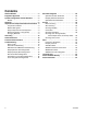
Contents Related Manuals . . . . . . . . . . . . . . . . . . . . . . . . . . . 3 Equipment Approvals . . . . . . . . . . . . . . . . . . . . . . . 3 System Configuration and Part Numbers . . . . . . . 4 Models . . . . . . . . . . . . . . . . . . . . . . . . . . . . . . . . 4 Warnings . . . . . . . . . . . . . . . . . . . . . . . . . . . . . . . . . 6 Important Two-Component Material Information . 9 Isocyanate Conditions . . . . . . . . . . . . . . . . . . . . . 9 Material Self-ignition . . . . . . . . . . .
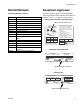
Related Manuals Related Manuals Equipment Approvals Component Manuals in English Equipment approvals appear on the following labels which are attached to the Fluid Station Control Box and EasyKey™. See FIG. 1 on page 4 for label locations.
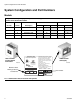
System Configuration and Part Numbers System Configuration and Part Numbers Models The part number for your equipment is printed on the equipment identification labels. See FIG. 1 for location of the identification labels. Meter Part No.
System Configuration and Part Numbers Hazardous Location Approval Models using a G3000, G3000HR, or intrinsically safe Coriolis meter are approved for installation in a Hazardous Location - Class I, Div I, Group D, T3 or Zone I Group IIA T3. Maximum Working Pressure Maximum working pressure rating is dependent on the fluid component options selected. The pressure rating is based on the rating of the lowest rated fluid component. Refer to the component pressure ratings below.
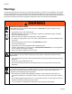
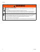
Warnings Warnings The following warnings are for the setup, use, grounding, maintenance, and repair of this equipment. The exclamation point symbol alerts you to a general warning and the hazard symbols refer to procedure-specific risks. When these symbols appear in the body of this manual, refer back to these Warnings. Product-specific hazard symbols and warnings not covered in this section may appear throughout the body of this manual where applicable.
Warnings WARNING SKIN INJECTION HAZARD High-pressure fluid from gun, hose leaks, or ruptured components will pierce skin. This may look like just a cut, but it is a serious injury that can result in amputation. Get immediate surgical treatment. • Do not spray without tip guard and trigger guard installed. • Engage trigger lock when not spraying. • Do not point gun at anyone or at any part of the body. • Do not put your hand over the spray tip.
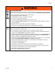
Warnings WARNING TOXIC FLUID OR FUMES HAZARD Toxic fluids or fumes can cause serious injury or death if splashed in the eyes or on skin, inhaled, or swallowed. • Read MSDSs to know the specific hazards of the fluids you are using. • Store hazardous fluid in approved containers, and dispose of it according to applicable guidelines. • Always wear chemically impermeable gloves when spraying, dispensing, or cleaning equipment.
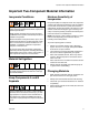
Important Two-Component Material Information Important Two-Component Material Information Isocyanate Conditions Spraying or dispensing materials containing isocyanates creates potentially harmful mists, vapors, and atomized particulates. Read material manufacturer’s warnings and material MSDS to know specific hazards and precautions related to isocyanates. Prevent inhalation of isocyanate mists, vapors, and atomized particulates by providing sufficient ventilation in the work area.
Grounding Grounding NOTE: If a Dose Time alarm (E-7, E-8) occurs, clear the alarm. 3. Do a complete system purge, following the instructions under Purging Using Recipe 0, in the ProControl 1KS Operation Manual. Your system must be grounded. See the Grounding instructions in your ProControl 1KS Installation manual. Check Resistance 4. Shut off the fluid supply to the solvent purge valve (SPV) and the air supply to the air purge valve (APV), FIG. 3. 5.
Pressure Relief Procedure Color Solenoid Identification Label Catalyst Color Solenoid Identification Label TI12826a Solvent Solenoid Overrides FIG. 2: Color Change Solenoids Key: FIH MA Component A Meter DVA Component A Dose Valve SPV Solvent Purge Valve SS Solvent Purge Valve Solvent Supply Tube APV Air Purge Valve AT Air Purge Valve Air Supply Tube FIH Fluid Inlet Hose FOH Fluid Outlet Hose MA APV AT DVA SS FOH SPV TI15977a FIG. 3.
Pressure Relief Procedure 12 3A1164B
Troubleshooting Troubleshooting Table 1: System Alarm Codes Code Description Follow Pressure Relief Procedure, page 10, before cleaning, checking, or servicing equipment. NOTE: Do not use the fluid in the line that was dispensed off ratio as it may not cure properly. Alarm Codes Table 1 lists the system alarm codes. See the system operation manual for complete information on alarm troubleshooting.
Troubleshooting Solenoid Troubleshooting Dose Valve A Solenoid Purge Valve B Solenoid Purge Valve A Solenoid Dose Valve B Solenoid J9 J3 J12 J1 J14 J15 J8 CAN CAN Power Fiber Optic TI15916a FIG.
Troubleshooting NOTE: Refer to the Schematic Diagrams, page 26. If the dispense or purge valves are not turning on or off correctly, it could be caused by one of the following. Cause 1. Air regulator pressure set too high or too low. Solution Check air pressure. 80-90 psi (550-630 kPa, 5.5-6.3 bar) is commonly used. Do not go below 70 psi (490 kPa, 4.9 bar) or above 120 psi (0.8 MPa, 8 bar). 2.
Troubleshooting Wall Mount Fluid Manifold Troubleshooting See FIG. 5. Key: MA Component A Meter DVA Component A Dose Valve SPV Solvent Purge Valve SS Solvent Purge Valve Solvent Supply Tube APV Air Purge Valve AT Air Purge Valve Air Supply Tube FIH Fluid Inlet Hose FOH Fluid Outlet Hose FIH MA APV AT DVA SS FOH SPV TI15977a FIG. 5.
Troubleshooting EasyKey Barrier Board Diagnostics See FIG. 6 and Table 2 to troubleshoot the EasyKey barrier board. Also see the EasyKey Electrical Schematic on page 27 and the System Electrical Schematic on pages 28 and 29. J4, Pin 1 J1, Pin 1 D5 F1 F2 F4 F3 D4 J5, Pin 1 FIG. 6: 255786 EasyKey Barrier Board Table 2: EasyKey Barrier Board Diagnostics Connector Description Diagnosis J1 AC Power Input n/a J4 24 Vdc Power Input to EasyKey Display Board D5 turns on.
Troubleshooting EasyKey Display Board Diagnostics See FIG. 7 and Table 3 to troubleshoot the EasyKey display board. Also see the EasyKey Electrical Schematic on page 27 and the System Electrical Schematic on pages 28 and 29.
Troubleshooting Table 3: EasyKey Display Board Diagnostics Connector/ Indicator Description Connector/ Indicator Description J1 Graphic Display Backlight J9 24 Vdc Power Input/Alarm Output J4 Ribbon Cable to Membrane J10 RS485 Communication Terminals J5 Inputs and Outputs D7 (green) J6 Remote I/O LED turns on when power is supplied to board J7 Fiber Optic Cable Input (black) J8 Fiber Optic Cable Output (blue) 3A1164B D11 (yellow) LED blinks (heartbeat) when board is operating P1 Eth
Troubleshooting Discrete I/O Board Diagnostics See FIG. 8 and FIG. 9 to troubleshoot the Discrete I/O board. Also see the System Electrical Schematic on pages 28 and 29.
Digital Output Common/Power Special Output #1 Special Output #2 Special Output #3 Digital Output Common/Power Special Output #4 Troubleshooting JLS Digital Output Common/Power Flow Rate Alarm Output Flow Calibrate Active Fill Active Mix Ready Output LED D1 (green) Mix Active Output Purge/Recipe Change Active Output Digital Output Common/Power Recipe Change Input Recipe Bit 5 Input Recipe Bit 4 Input Recipe Bit 3 Input Recipe Bit 2 Input Recipe Bit 1 Input Recipe Bit 0 Input Digital Input Common
Troubleshooting Fluid Station Control Board Diagnostics See FIG. 10 and Table 4 to troubleshoot the fluid station control board. Also see the System Electrical Schematic on pages 28 and 29. J4 (Fiber Optic Output - blue) J1, Pin 1 D18 D19 F1 (Fuse) J6 (Fiber Optic Input black) D15 J10 (Power Input) D45 VDC D16 J11 (Color Change Module) D46 D17 D20 J7 (Not Used) D44 J9, Pin 1 D29 D43 D28 D30 J14, Pin 1 D27 J15, Pin 1 D41 D33 D31 J8, Pin 1 FIG.
Troubleshooting Table 4: Fluid Station Control Board Diagnostics LED Connector and Pin Nos. Signal Description Diagnosis D15 J1, 1 & 2 Air Flow Switch 1 Turns on when gun 1 is triggered. D16 J1, 5 & 6 Solvent Flow Switch Turns on when solvent is flowing. D17 J1, 9 & 10 Gun Flush Box 2 Pressure Switch Turns on when a gun is in Gun Flush Box 2. D18 J10 Power Turns on when power is supplied to the board. D19 n/a Communication (yellow) Turns on when board is communicating with EasyKey.
Troubleshooting Color Change Board Diagnostics See FIG. 11 and Table 5 to troubleshoot the color change board. Also see the System Electrical Schematic on pages 28 and 29. J8, Pin 1 D33 D34 D43 D31 D44 D29 J9, Pin 1 J15, Pin 1 D39 D41 D32 D35 D38 J16, Pin 1 D27 D37 J14, Pin 1 D45 D30 D46 D28 J10, Pin 1 D36 D9 D10 D8 F1 (Fuse) J7 J11 FIG.
Troubleshooting Table 5: Color Change Board Diagnostics LED Connector and Pin Nos. Board 1 Signal Description Board 2 Signal Description Diagnosis D8 n/a Board OK Board OK Blinks (heartbeat) during normal operation. D9 n/a Communication (yellow) Communication (yellow) Turns on when board is communicating with ProMix 2KS. D10 J7 Power Power Turns on when power is supplied to the board.
Schematic Diagrams Schematic Diagrams System Pneumatic Schematic COLOR CHANGE CONTROL AIR EXHAUST MUFFLER COLOR 1 COLOR 2 COLOR 3 COLOR 4 COLOR 5 COLOR 6 COLOR 7 COLOR 8 COLOR SOLVENT COLOR 9 COLOR 10 COLOR 11 COLOR 12 CATALYST 1 CATALYST 2 CATALYST 3 CATALYST 4 CATALYST SOLVENT 4-WAY SOLENOID A B E E OS CL UB 2T 5/3 N E OP E E OS CL UB 2T / 53 N E OP DOSE A VALVE 1/4 TUBE 12 VDC A B DOSE B VALVE 12 VDC 05 CONTROL AIR 3/8 AIR FILTER MANUAL DRAIN 5 MICRON WALL MOUNT ONLY 4-WAY SOLENOID AIR INP
3A1164B DISPLAY BOARD P1 BARRIER BOARD J9 1 2 3 4 RJ45 DISPLAY BOARD RJ45 J5 J1 J4 24 VDC+ IN RED 18 AWG BLACK 18 AWG RED/BLACK/WHITE 22 AWG J5-1 J5-2 J5-3 SHIELD/GRND COMMON (BLACK) +12 VDC I/S (WHITE) UNUSED UNUSED J1-1 UNUSED J1-2 UNUSED J1-4 J1-3 UNUSED RED 18 AWG BLACK 18 AWG J1-5 J4-1 J4-2 J4-3 GREEN/BLACK/WHITE 22 AWG IS POWER 12 VDC + + + + - RED 18 AWG BLACK 18 AWG DC OK + - - 24 VDC+ HIGH VOLTAGE IN POWER SUPPLY 24 VDC+ OUTPUT GND LUG COMMON R
Schematic Diagrams System Electrical Schematic NOTE: The electrical schematic illustrates all possible wiring expansions in a ProMix 2KS system. Some components shown are not included with all systems.
Schematic Diagrams System Electrical Schematic NOTE: The electrical schematic illustrates all possible wiring expansions in a ProMix 2KS system. Some components shown are not included with all systems.
Service Service Before Servicing 3. Shut off ProControl 1KS power (0 position). FIG. 12. 4. If servicing EasyKey, also shut off power at main circuit breaker. • • • • • To avoid electric shock, turn off EasyKey power before servicing. Servicing EasyKey display exposes you to high voltage. Shut off power at main circuit breaker before opening enclosure. All electrical wiring must be done by a qualified electrician and comply with all local codes and regulations.
Service Servicing EasyKey 5. Disconnect graphic display power cable (J1) from the display board (210c). Updating Software 6. Separate graphic display (210b) from display board (210c) [connector J2 on back of board]. To update software, upload new software from your PC using the basic web interface. See manual 313386. NOTE: If using the Graco Gateway in your system, disconnect its cable from the EasyKey before updating the ProControl 1KS software. 7.
Service Replacing Line Filter Replacing Power Switch 1. Follow Before Servicing, page 30. 1. Follow Before Servicing, page 30. 2. Unlock and open EasyKey door with its key. 2. Unlock and open EasyKey door with its key. 3. Note position of line filter input and output wires. See EasyKey Electrical Schematic, page 27. Disconnect wires and remove line filter (214l) from bracket (214m). See FIG. 14. 3. Note position of power switch wires. See EasyKey Electrical Schematic, page 27.
Service Replacing Barrier Board 8. Install the cover (214b) with 2 screws (214k), using the security tool. 9. Connect cables to J1, J4, and J5. 10. Close and lock EasyKey door with key. 11. Turn on power at main circuit breaker. NOTICE To avoid damaging circuit board when servicing, wear Part No. 112190 grounding strap on wrist and ground appropriately. 12. Turn EasyKey power on to test operation. Replacing Barrier Board Fuses 1. Follow Before Servicing, page 30. 2.
Service J4 (Power to Display Board) J1 (Power In) 214g 214g F2 F1 F4 F3 214h J5 (Power to Fluid Station) 214g Do not remove this screw 214h Front of Barrier Board, showing Fuses and Connectors 1 1 Z Apply thermal compound to surface of heatsink (Z). Back of Barrier Board, showing Heatsink (Z) FIG.
Service Control Box 2. Disconnect fiber optic wires (J4, J6) and all cables (J1, J3, J5, J7, J8, J9, J10, J12, J14, J15) from control board (302). FIG. 17. Replacing Control Board 3. Remove 4 screws (303). Remove connector jam nuts on the outside of the enclosure (301). Remove control board (302). FIG. 18. 4. Install new control board (302) with 4 screws (303). NOTICE To avoid damaging circuit board when servicing, wear Part No. 112190 grounding strap on wrist and ground appropriately. 1.
Service 309 310 311 330 TI15974a 301 313 326 303 304 302 334 306 305 320 343 F1 325 TI15916a 307 312 315 333 308 332 318 334 314 317 319 316 TI15917a FIG.
Service Replacing Solenoids The Fluid Station Control Box has a minimum of 4 solenoids. If you have options installed, you have additional (optional) solenoids for each. See Table 6 and Schematic Diagrams, page 26. To replace a single solenoid: Table 6: Control Box Solenoids Solenoid Actuates Standard 1 Dose Valve A 2 Dose Valve B 3 Air Purge Valve 4 Solvent Purge Valve Optional 1. Follow Before Servicing, page 30, and shut off power at main circuit breaker.
Service Servicing Flow Meter NOTE: To avoid leakage, secure the meter (M) to the dose valve connector (H) before connecting it to the fluid station. 2. Secure meter (M) and plate (MP) to bracket with screws (MS). Coriolis Meter 3. Connect meter cable (CC). See FIG. 20. 1. Follow Before Servicing, page 30. 4. Connect fluid line (P). 2. To remove and service the Coriolis meter, see manual 313599. 5. Calibrate meter as instructed in ProControl 1KS Operation manual.
Service Servicing Color Change Module, Color/Catalyst Valves, and Dump Valves 1. Follow Before Servicing, page 30. 2. See manual 312787 for the color change module. 3. See manual 312783 for the color/catalyst valve stacks. 4. See manual 312786 for the dump valve kits. 5. See manual 312782 to service an individual valve.
Service Servicing Flow Control 6. Install a new o-ring (602) on the pressure sensor (620) and screw the sensor into the fluid plate (606). Preparation 7. Reinstall the fluid plate on the air plate. Be careful not to pinch the pressure sensor cable. Torque the screws (605) to 30-40 in-lb (3.4-4.5 N•m). 8. Reconnect the three cables to J1, J2, and J4 on the circuit board (618). FIG. 22. 1. Follow Before Servicing, page 30. 2. Disconnect all air and fluid lines from the flow control regulator. 3.
Service Servicing the V/P Valve 615 1. Follow Before Servicing, page 30. 2. Remove the four screws (605) holding the bracket (614) to the housing (611). FIG. 23. 3. Carefully separate the bracket from the housing and disconnect the V/P valve cable from J2 on the circuit board (618). FIG. 22. *613 604* *610 Flow direction 606 4. Remove the two screws (619a) and o-rings (619b). Install the new valve (619) with new screws and o-rings. *609 602*‡ *612 620*‡ *617 *623 *616 5.
Service 42 3A1164B
Parts Parts ProControl 1KS System The part number for your equipment is printed on the equipment identification labels. See FIG. 1 for location of the identification labels. Meter Part No.
Parts Part No. 262380, without meter or flow control Part No. 262381, with G3000 meter, without flow control Part No. 262382, with G3000 meter and flow control Part No. 262383, with Coriolis meter and flow control 5 2 3 24 2 336 335 17 4 1 11 2 9 10 8 2 Items 335 and 336 are part of the Fluid Station Control Box. See the parts list beginning on page 49 for descriptions.
Parts Part No. 262380, without meter or flow control Part No. 262381, with G3000 meter, without flow control Part No. 262382, with G3000 meter and flow control Part No. 262383, with Coriolis meter and flow control Ref. No. 1 2 3 4 5 6 6a 8 9 Part No.
Parts EasyKey Controls 277869 EasyKey, with Display 206 Detail of Display Interface Kit (210) 214f 214c 208 201 210a 210d 202 214h 214l, 214m 210b 210c 210e TI12554a 214g 214a 211 221 214b TI12417b 214k 201 214d 214f 212 203 218 214l, 214m 209 214e, 214j 207 205, 206, 209 213, 223, 206 46 204 215 221 211 TI12496b 3A1164B
Parts 277869 EasyKey, with Display Ref. No. Part No.
Parts 262363 Fluid Station Control Box 309 310 311 330 TI15974a 301 313 326 303 304 302 334 305 306 343 320 325 TI15916a 312 333 307 315 308 332 318 334 314 317 48 319 316 TI15917a 3A1164B
Parts 262363 Fluid Station Control Box NOTE: Parts are shown on page 48, unless noted. Ref. No. Part No. Description 301 302 303 16E380 ENCLOSURE 255765 BOARD, circuit n/a SCREW, machine, pan hd; 4-40 x 3/16 in.
Parts 262364 Valve Stack Ref. No. 401 402 403 404 405‡ 406 407‡ 408 409 410 411 Part No. Description Qty 15X303 VALVE, high pressure; includes item 413; see manual 312782 --SCREW; 5/16-24 x 5/8 in. (16 mm) 15T436 ADAPTER, manifold 101970 PLUG, pipe 109450 O-RING; ptfe 15T869 MANIFOLD, fluid port --SEAT, valve needle; sst 110004 O-RING; ptfe 15T872 MANIFOLD, body --SCREW, cap, socket-head; 1/4-20 x 5/8 in. (16 mm) 15T871 MANIFOLD, end cap 3 8 3 3 6 1 3 3 2 6 Ref. No. Part No.
Parts 249849 Flow Control Regulator Ref. No. Part No. Description 601* 102980 602‡* n/a NUT, full, hex; 4-40 O-RING; chemically resistant fluoroelastomer 603 112698 ELBOW; 1/8 npt(m) x 1/4 in. (6 mm) OD tube 604* n/a O-RING; chemically resistant fluoroelastomer 605 n/a SCREW, cap, socket-hd; 10-32 x 1/2 in.
Parts 52 3A1164B
Technical Data Technical Data Maximum fluid working pressure . . . . . . . . . . . . . . . Base system: 4000 psi (27.58 MPa, 275.8 bar) Low pressure color change: 300 psi (2.07 MPa, 20.6 bar) Coriolis meter: 2300 psi (15.86 MPa, 158.6 bar) Flow control: 190 psi (1.31 MPa, 13.1 bar) Maximum working air pressure. . . . . . . . . . . . . . . . . 100 psi (0.7 MPa, 7 bar) Air supply . . . . . . . . . . . . . . . . . . . . . . . . . . . . . . . . . 75 - 100 psi (0.5 - 0.7 MPa, 5.
Graco Standard Warranty Graco warrants all equipment referenced in this document which is manufactured by Graco and bearing its name to be free from defects in material and workmanship on the date of sale to the original purchaser for use. With the exception of any special, extended, or limited warranty published by Graco, Graco will, for a period of twelve months from the date of sale, repair or replace any part of the equipment determined by Graco to be defective.