
User's Manual

Service
34 3A1164B
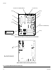
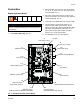
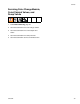
FIG. 16: Barrier Board Connectors and Fuses
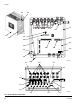
Do not remove
this screw
J1 (Power In)
J4 (Power to Display Board)
J5
(Power to Fluid Station)
F1
F2
F3
F4
214h
214h
214g
214g
214g
Back of Barrier Board, showing Heatsink (Z)
Z
1
Front of Barrier Board, showing Fuses and Connectors
Apply thermal compound
to surface of heatsink (Z).
1