
User's Manual

Service
3A1164B 35
Control Box
Replacing Control Board
1. Follow Before Servicing, page 30.
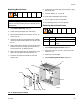
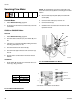
2. Disconnect fiber optic wires (J4, J6) and all cables
(J1, J3, J5, J7, J8, J9, J10, J12, J14, J15) from con-
trol board (302). F
IG. 17.
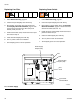
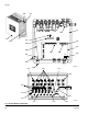
3. Remove 4 screws (303). Remove connector jam
nuts on the outside of the enclosure (301). Remove
control board (302). F
IG. 18.
4. Install new control board (302) with 4 screws (303).
5. Connect cables to control board (302). F
IG. 17.
Insert fiber optic cable connectors (J4, J6) into
board connectors (E), matching blue with blue, black
with black, and hand-tighten connectors. Do not
pinch or kink the fiber optic cables; the cables
require a 2 in. (51 mm) bend radius.
6. Turn EasyKey power on to test operation.
NOTICE
To avoid damaging circuit board when servicing, wear
Part No. 112190 grounding strap on wrist and ground
appropriately.
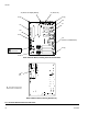
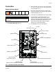
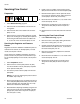
FIG. 17: 255765 Fluid Station Control Board
J6
(F.O. Input - black)
J4
(F.O. Output - blue)
J10
(Power Input)
J5
(Flow Control)
J11
(Color Change Module)
J7
(Not Used)
J15
(Solenoid Output:
3rd Flush Valve: Dump Valve A)
J8
(Solenoid Output: Dump Valve B)
J14
(Solenoid Output:
Air Purge Valve and Solvent Flush Valve)
J1
(Digital Input)
J9
(Solenoid Output:
Dose Valves A and B)
J3
(Meter A and B Input)
J12
(Solvent Meter Input)
J13
(Not Used)
F1 (343)