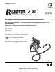
Repair-Parts ® A-25 3A1570A PLURAL COMPONENT PROPORTIONER EN Air operated, electrically heated, plural component proportioner For spraying or dispensing 1:1 ratio polyurethane foam formulations and other 1:1 fast setting materials. Not for use in explosive atmospheres or hazardous locations. This model is field-configurable to the following supply voltages: 230 V, 1 Phase 230 V, 3 Phase 380 V, 3 Phase 2000 psi (14 MPa, 138 bar) Maximum Fluid Working Pressure 80 psi (550 kPa, 5.
Contents Proportioner Models . . . . . . . . . . . . . . . . . . . . . . . . 3 Systems . . . . . . . . . . . . . . . . . . . . . . . . . . . . . . . . . . 3 Related Manuals . . . . . . . . . . . . . . . . . . . . . . . . . . . 3 Warnings . . . . . . . . . . . . . . . . . . . . . . . . . . . . . . . . . 4 Important Two-Component Material Information . 7 Isocyanate Conditions . . . . . . . . . . . . . . . . . . . . . 7 Material Self-ignition . . . . . . . . . . . . . . . . . . . . . .
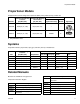
Proportioner Models Proportioner Models All proportioners can be configured to operate on 380V (4 wire), 230V (3 wire), or 230V 1Ø. Maximum Fluid Working Maximum Air Working Pressure Set Pressure psi (MPa, bar) psi (kPa, bar) Part No. Includes: DataTrak (cycle count only) Wheels 262572 2000 psi (14, 138) 80 psi (550, 5.5) --- --- 262614 2000 psi (14, 138) 80 psi (550, 5.5) 24A592 Approvals 3172585 Only available in Asia.
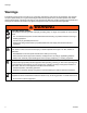
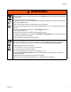
Warnings Warnings The following warnings are for the setup, use, grounding, maintenance, and repair of this equipment. The exclamation point symbol alerts you to a general warning and the hazard symbols refer to procedure-specific risks. When these symbols appear in the body of this manual, refer back to these Warnings. Product-specific hazard symbols and warnings not covered in this section may appear throughout the body of this manual where applicable.
Warnings WARNING FIRE AND EXPLOSION HAZARD Flammable fumes, such as solvent and paint fumes, in work area can ignite or explode. To help prevent fire and explosion: • Use equipment only in well ventilated area. • Eliminate all ignition sources; such as pilot lights, cigarettes, portable electric lamps, and plastic drop cloths (potential static arc). • Keep work area free of debris, including solvent, rags and gasoline.
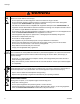
Warnings WARNING EQUIPMENT MISUSE HAZARD Misuse can cause death or serious injury. • Do not operate the unit when fatigued or under the influence of drugs or alcohol. • Do not exceed the maximum working pressure or temperature rating of the lowest rated system component. See Technical Data in all equipment manuals. • Use fluids and solvents that are compatible with equipment wetted parts. See Technical Data in all equipment manuals. Read fluid and solvent manufacturer’s warnings.
Important Two-Component Material Information Important Two-Component Material Information Isocyanate Conditions Spraying or dispensing materials containing isocyanates creates potentially harmful mists, vapors, and atomized particulates. Read material manufacturer’s warnings and material MSDS to know specific hazards and precautions related to isocyanates. Prevent inhalation of isocyanate mists, vapors, and atomized particulates by providing sufficient ventilation in the work area.
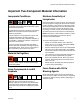
Important Two-Component Material Information Changing Materials Changing the material types used in your equipment requires special attention to avoid equipment damage and downtime. • When changing materials, flush the equipment multiple times to ensure it is thoroughly clean. • Always clean the fluid inlet strainers after flushing. • Check with your material manufacturer for chemical compatibility.
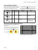
Important Two-Component Material Information DataTrak Diagnostic Codes DataTrak can diagnose several problems with the pump. When the monitor detects a problem, the LED will flash and a diagnostic code will appear on the display. Symbol Code To acknowledge the diagnosis and return to the normal operating screen, press once to wake up the display, and once more to clear the diagnostic code screen. Code Name Diagnosis Cause E-2 Diving Down Leak during downstroke. Worn intake valve.
Important Two-Component Material Information E01: High fluid temperature Causes of E01 Errors • Thermocouple A or B (361) senses a fluid temperature above 230°F (110°C). • Fluid temperature sensor (FTS) senses a fluid temperature above 230°F (110°C). • Overtemperature switch (359) senses a fluid temperature above 230°F (110°C) and opens. At 190°F (87°C) the switch closes again.
Important Two-Component Material Information d. If the swapped module does not fix the problem, the power module is not the cause. 8. Verify continuity of heater elements with an ohmmeter, see page 28. E02: High zone current 1. Turn main power OFF . 2. Relieve pressure, page 13. NOTE: Disconnect whip hose. 3. Disconnect hose connector (D) at Reactor. 4. Using an ohmmeter, check between the two terminals of the connector (D). There should be no continuity. 5. Exchange zone module with another one.
Important Two-Component Material Information E05: Control board over temperature NOTE: Each module has an on-board temperature sensor. Heat is turned off if module temperature exceeds 185°F (85°C) within the heater module. 1. Check that fan above electrical cabinet is operating. 2. Check that electrical cabinet door is properly installed. 3. Check for obstructions blocking cooling holes in bottom of electrical cabinet. 4. Clean heatsink fins behind heater control modules. 5.
Before Beginning Repair Before Beginning Repair 5. Close gun fluid inlet valves A and B. Repairing this equipment requires access to parts that may cause electric shock or other serious injury if work is not performed properly. Electrical troubleshooting must be done by a qualified electrician. Be sure to shut off all power to equipment and lock out power at the source before repairing. 1. Flush if necessary. See Flushing, page 14. 2. Turn main heater power OFF ti2421a 6.
Park Park Flushing Park the pumps at the end of the day to cycle component A pump to home position, submerging displacement rod. Flush equipment only in a well-ventilated area. Do not spray flammable fluids. Do not turn on heaters while flushing with flammable solvents. 1. Open the park valve. Open • Flush out old fluid with new fluid, or flush out old fluid with a compatible solvent, such as toluene, naptha, or mineral spirits before introducing new fluid.
Troubleshooting Troubleshooting Problems Before performing any troubleshooting procedures: 1. Relieve pressure, page 13. 2. Turn main power OFF Try the recommended solutions in the order given for each problem, to avoid unnecessary repairs. Also, determine that all circuit breakers, switches, and controls are properly set and wiring is correct before assuming there is a problem. . 3. Allow equipment to cool.
Troubleshooting PROBLEM Fluid pressure low or dropping CAUSE Air supply pressure low when spraying SOLUTION Increase inlet air pressure Increase air compressor size to meet flow requirements Remove airline quick disconnects Use 3/8 in. (0.95 cm) ID or larger air supply hose. Use 1/2 in. (12.7 mm) if longer than 25 ft (7.6 m). Icing in air motor exhausts or mufflers Check inlet filter water separator; see page 25. Stop spraying while ice melts.
Troubleshooting PROBLEM Fluid pressures not balanced between A and B side CAUSE Fluid viscosities not equal SOLUTION Adjust A and B temperature settings to balance viscosity.
Troubleshooting Problem Erratic display; display turns on and off. Hose display reads OA at startup. Display does not respond properly to button pushes. Cause Solution Low voltage. Ensure input voltage is within specifications, page 36. Poor display connection. Check cable connections, page 36. Replace damaged cable. Display cable damaged or corroded. Clean connections; replace cable if is damaged. Display cable not grounded. Ground cable, page 37. Display extension cable too long.
Troubleshooting Heater PROBLEM CAUSE SOLUTION Heat turned off. Press Primary heater(s) does not heat. Control of primary heat is abnormal; high temperature overshoots or E01 error occurs intermittently. 3A1570A A or B zone keys. Temperature control alarm. Check temperature display for diagnostic code, page 9. Signal failure from thermocouple. See E04: Fluid Temperature Sensor (FTS) or thermocouple disconnected, page 11. Dirty thermocouple connections.
Troubleshooting Hose Heat System PROBLEM Hose heats but heats slower than usual or it does not reach temperature. Hose does not maintain temperature while spraying. CAUSE Ambient temperature is too cold. Use auxiliary hose heat system. FTS failed or not installed correctly. Check FTS, page 11. Low supply voltage. Verify line voltage. Low line voltage significantly reduces power available to hose heat system, affecting longer hose lengths. A and B setpoints too low. Increase A and B setpoints.
Troubleshooting PROBLEM CAUSE FTS failed or is not contacting correctly. Check FTS, page 11. FTS not installed correctly. FTS should be installed close to end of hose in same environment as gun. Verify FTS installation, page 32. Temperature control alarm. Check temperature display or diagnostic code, page 32. Shorted connection or failed hose heating element. With hose heat on and temperature setpoint above displayed hose zone temperature, verify voltage between connectors at each section of hose.
Repair Repair 6. Shut off inlet air ball valve (G) Unless otherwise noted, all repair procedures must be completed with incoming power switched OFF and locked out at the source. Any electrical repair or troubleshooting required beyond the scope of this manual must be performed by a qualified electrician. Shut off air inlet ball valve and shut off all air supply pressure. 7. Remove screws (13, 15) and pump covers (63).
Repair 11. Push retaining wire clip (307) up. Push retaining pin (306) out. 5. For Iso A pump only: a. Install two pipe plugs (324). 307 b. Reconnect two tubing lines (N) from ISO Pump Lube reservoir. Flush and refill reservoir with TSL 206995. 6. Refill Resin B pump wet cup with TSL 206995. 306 301 302 304 303 ti17991a 12. Loosen lock nut (302) by hitting firmly with a non-sparking hammer. 13. Unscrew pump out of pump mounting plate (301). 14.
Repair Remove Air Motor 1. Press in tube fitting ferrules and pull out tubing (65) to disconnect air line. 6. Lay air motor on a clean flat work space. Place a wrench on the tie rod flats (309) and hold one of other tie rods with your hand to keep the air motor (308) in place. Remove the tie rods from the air motor. 2. Disconnect DataTrak communication cable, if installed. 3. Place wrench on adapter (315) and a another wrench on lock nut (313). Remove lock nut (313). 309 315 313 308 ti17992a FIG.
Repair Recirculation / Over Pressure Relief Block Air Inlet Filter / Water Separator (Auto Drain) Valves can be serviced with the block on the machine (see page 46 for parts view). For thorough cleaning, remove the block assembly as follows. Air Filter Element Removal 1. Disconnect two fluid tubes connected to back of recirculation block (3). 2. Hold in metal spring clip and twist black cover counterclockwise to remove. 1. Close air inlet valve (302) on filter (301). 2.
Repair Temperature Control Module A B Table 2: Temperature Control Module Connections Connector Description DATA (A) Data reporting PIN 12 11 10 C H HOSE T/C P; FTS (purple) HOSE T/C R; FTS (red) HOSE T/C S; FTS (silver (unshielded bare wire)) 9 HEATER T/C B, Y; Thermocouple (yellow) SENSOR (B) 8 HEATER T/C B, R; Thermocouple (red) 7 Not used 6 HEATER T/C A, Y; Thermocouple (yellow) 5 HEATER T/C A, R; Thermocouple (red) 4, 3 OVERTEMPERATURE B; Overtemperature switch B 2, 1 OVERTEMPERATURE A; Overte
Repair Test SCR Circuit Replacing Temperature Control Assembly Modules 1. Test the SCR circuit in the on position: a. Make sure everything is connected, including the hose. NOTICE b. Turn main power ON . c. Adjust the hose heat setpoint above the ambient hose temperature. Before handling assembly, put on static conductive wrist strap to protect against static discharge which can damage assembly. Follow instructions provided with wrist strap. 1. Turn main power off d.
Repair Primary Heater Line Voltage The primary heaters output their rated wattage at 230 Vac. Low line voltage will reduce power available and the heaters will not perform at full capability. Read Warnings on page 4. Wait for heater to cool before repairing. Heater Element 1. Turn main power OFF . Disconnect power supply. 2. Relieve pressure, page 13. 3. Wait for heaters to cool. 4. Remove heater shroud. 5. See FIG. 7. Disconnect heater element wires from heater wire connector. Test with ohmmeter.
Repair 353 1 6 5 361 356 357 6 362 359 2 5 354 355 3 6 7 352 351 1 Torque to 120 ft-lbs (163 N•m). 2 Torque to 23 ft-lbs (31 N•m). 3 Torque to 40 ft-lbs (54 N•m). 4 Apply 110009 thermal heatsink compound. 5 Apply sealant and PTFE tape to all non swiveling and threads without o-rings. 6 Apply lubricant to o-rings. 7 Orient rupture disc housing (369) with exhaust hole pointing towards the bottom of the heater. 6 360 1 358 ti17998a FIG. 7.
Repair Thermocouple 8. Replace thermocouple, FIG. 8. Read Warnings on page 4. Wait for heater to cool before repairing. 1. Turn main power OFF a. Remove protective tape from thermocouple tip (T). b. Apply PTFE tape and thread sealant to male threads and tighten thermocouple housing (H) into adapter (356). c. Push in thermocouple (361) so tip (T) contacts heater element (358). . Disconnect power supply. 2. Relieve pressure, page 13. d.
Repair Overtemperature Switch 5. If hose fails test, retest at each length of hose, including whip hose, until failure is isolated. Check FTS Cables Read Warnings on page 4. Wait for heater to cool before repairing. 1. Turn main power OFF . Disconnect power supply. 1. Turn main power OFF . Disconnect power supply. 2. Relieve pressure, page 13. 3. Disconnect FTS cable (F) at Reactor, FIG. 9. 2. Relieve pressure, page 13. 3. Wait for heaters to cool. F 4. Remove heater shroud. 5.
Repair Fluid Temperature Sensor (FTS) 4. If FTS fails any test, replace FTS. Test/Removal 5. Disconnect air hoses (C, L), and electrical connectors (D). 1. Turn main power OFF 6. Disconnect FTS from whip hose (W) and fluid hoses (A, B). . Disconnect power supply. 7. Remove ground wire (K) from ground screw on underside of FTS. 2. Relieve pressure, page 13. 8. Remove FTS probe (H) from component A (ISO) side of hose. 3. Remove tape and protective covering from FTS. Disconnect hose cable (F).
Repair Transformer Primary Check 1. Turn main power OFF 3. To verify transformer voltage, turn on hose zone. Measure voltage from 178CB-2 to HPOD-1; see Reactor A-25 Wiring Schematic, page 51. . Model Secondary Voltage 310 ft. 90 Vac* 210 ft. 62 Vac* 2. Locate the two smaller (10 AWG) wires coming out of transformer. Trace these wires back to contactor and circuit breaker (911). Use an ohmmeter to test for continuity between two wires; there should be continuity. * For 230 Vac line voltage.
Repair Replace Circuit Breaker Module 1. Turn main power OFF . Disconnect power supply. Turn circuit breakers on to test. 2. Relieve pressure, page 13. 3. Using an ohmmeter, check for continuity across circuit breaker (top to bottom). If no continuity, trip breaker, reset, and retest. If still no continuity, replace breaker as follows: a. Refer to electrical diagrams and table below. Disconnect wires and remove bad breaker.
Repair Pump Lubrication System ST Check the condition of the ISO pump lubricant daily. Change the lubricant if it becomes a gel, its color darkens, or it becomes diluted with isocyanate. Gel formation is due to moisture absorption by the pump lubricant. The interval between changes depends on the environment in which the equipment is operating. The pump lubrication system minimizes exposure to moisture, but some contamination is still possible.
Repair Fluid Inlet Strainer Screen Temperature Display The inlet strainers filter out particles that can plug the pump inlet check valves. Inspect the screens daily as part of the startup routine, and clean as required. Isocyanate can crystallize from moisture contamination or from freezing. If the chemicals used are clean and proper storage, transfer, and operating procedures are followed, there should be minimal contamination of the A-side screen.
Repair 116 119 G 106 105 107 104 102 103 ti18026a Detail of Membrane Switches and Temperature Display Board Temperature Display 102a 102b 102c 1 R ti18003a FIG. 15.
Repair Replace DataTrak Battery or Fuse 4. Remove two screws on back of module to access battery. The battery and fuse must be replaced in a non-hazardous location. 5. Disconnect the used battery and replace with an approved battery. See FIG. 18. Use only the following approved replacement batteries. Use of an unapproved battery will void Graco’s warranty and FM and Ex approvals. • Ultralife lithium # U9VL • Duracell alkaline # MN1604 • Energizer alkaline # 522 • Varta alkaline # 4922 Replace Fuse 1.
Accessories Accessories Feed Pump Kits P2 Spray Gun Pumps, hoses, and mounting hardware to supply fluids to Reactor. Includes 246483 Air Supply Kit. See 309815. Probler P2 Gun available in round or flat pattern. See 313213. 246483 Air Supply Kit Y-Strainer Screen Hoses and fittings to supply air to feed pumps, agitator, and gun air hose. Included in feed pump kits. See 309827. Replacement strainer screen for fluid Y-strainer; 20 mesh.
Parts Parts 262572, Bare Reactor A-25 262614, Reactor A-25 with DataTrak and Wheels 66 67 1 6 14 (x4) 10 50 57 58 20 20 18 57 83 3 56 (x4) 62 51 4 38 11 84 79 16 11 (x6) 62 35 52 100 (x4) 59 9 (x4) 88 8 7 17 85 26 13 91, 92 ti18023a 15 40 15 19 89 90 (x6) 3A1570A
Parts 5 25 (x2) 93 24 13 (x2) 7 2 68 69 23 22 3 15 63 61 21 1 94 9 (x4) 15 63 1 Torque pump locking nuts to 66-74 ft-lbs (90-100 N•m). 2 Apply anaerobic polyacrylate pipe sealant to all non-swiveling pipe threads. 3 Torque tube ends to 212-265 in-lbs (24-30 N•m). 4 Connect ground wire (94) from motor lug to ground lug in cabinet.
Parts 98 33 60 49 37 34 ti18025a 13 (x4) 10 83 13 (x4) 49 12 30 5 27 31 32 29 28 80 ti18007a 262572, Bare Reactor A-25 262614, Reactor A-25 with DataTrak and Wheels Ref Part Description Qty. 1 2 3 4 --262573 262577 --- 1 1 1 1 5 24J788 6 7 8 262575 262576 24M177 CART PUMP; see page 48 MANIFOLD, relief; see page 46 PANEL, control, heater; see page 45 HEATER, system, (6.
Parts 17 18 19 20 21 22 23 24 25 26 27 28 29 30 31 32 33 34 35 36 37† 38 44‡ 45‡ 49 50 51 123970 123971 123972 205447 16G921 16G922 16G923 16G924 112125 117666 15D795 107128 114110 162449 158491 262660 114269 16G918 246995 234366 262695 16M152 247791 261669 167002 16J433 16J434 52 53‡ 54‡ 55‡ 56 57 261821 --206994 206995 186494 --- 58 59 60 61 62 63 64 15G280 189930 189285 15H108 15B380 16G952 --- 65 --- 66 --67† 24B563 68† 24B659 3A1570A SWITCH, disconnect, 40a KNOB, disconnect, operator S
Parts Control Panel, 262575 105 116 104 102 106 3 119 4 2 1 ir 101 113 118 A 106 Fl 103 ow 107 110 1 109 111 113 1 108 113 1 Apply sealant to all non swiveling pipe threads. 2 Attach ground wire from harness (116) between connector on harness (106) and display cover (105). 3 Attach harness (106) to J13 on board (102). 4 Attach harness (119) to J1 on board (102). 114 113 115 112 ti18002a 121 Ref.
Parts Temperature Control 151 152 Wheel Kit, 262695 155 154 195 To B Heater Module 193 153 To A Heater Module 194 192 194 191 193 To Hose Heater Module 154 Ref. Part 151 16G925 152 247827 153 247828 154 114183 155 247801 3A1570A Description PANEL, pod, mounting MODULE, heater control MODULE, heater NUT, hex, flanged, serrated CABLE, communication Qty. 1 1 3 4 1 ti18006a Ref.
Parts Fluid Manifold 4 Fluid Inlet Kit, 262695 212 214 4 205 255 3 208b 208 204 213 1 2 208a 3 1 203 254 253 201 ti18027a 252 206 251 210 209 202 1 Assemble ball valves in orientation shown. 2 Apply anaerobic polyacrylate pipe sealant to all NPT connections. ti8459a 207 1 Apply sealant and torque to 250 in-lbs (28 N•m). 2 Use blue thread lock on valve cartridge threads into manifold. 3 Part of item 208. 4 Apply lubricant to mating surfaces.
Parts 6 kw Dual Zone Heater, 24J788 353 1 6 5 361 356 357 6 362 359 2 5 354 355 3 6 7 352 351 1 Torque to 120 ft-lbs (163 N•m). 2 Torque to 23 ft-lbs (31 N•m). 3 Torque to 40 ft-lbs (54 N•m). 4 Apply 110009 thermal heatsink compound. 5 Apply sealant and PTFE tape to all non swiveling and threads without o-rings. 6 Apply lubricant to o-rings. 7 Orient rupture disc housing (369) with exhaust hole pointing towards the bottom of the heater.
Parts A-25 Air Motor Pump Assembly, 262573 314 308 316 325 3 313 305 315 3 313 3 7 319 305 314 311 306 4 2 307 309 301 310 6 312 302 5 318 324 322 Ref Part Description Qty.
Parts Air Tubing Connections 503 502 500 502 501 500 503 501 Ref. 64 65 65 65 3A1570A Length ft (m) 0.75 ft (0.23 m) 2.66 ft (0.8 m) 1.66 ft (0.5 m) 0.75 ft (0.23 m) Connection From 503 501 502 500 To 503 501 502 500 Material UHMWPE Urethane Urethane Urethane Color Black Black Black Black Outside Diameter 5/32 in. (4 mm) 1/2 in. (12.7 mm) 1/2 in. (12.7 mm) 1/2 in. (12.
Parts Breaker Module, 262576 404 (8x) 403 410 (4x) 404 (7x) 403 403 413 411 412 414 405 402 409 Ref. Part Description Qty.
3A1570A 179-5 179-4 179-3 179-2 179-1 179 178 177 176 175 174 173 172 171 170 TB19 2 BRIDGES N 180 185 190 DSC 1-4 HOSE HEATER 20 20 BRIDGE 207 FTS TB9-2 FU1-2 4 178CB 2 TB10-2 FU2-2 30A 3 1 FUSE1 FU1-1 L1 BRIDGE FUSE2 FU2-1 TB13-19 PE TB13 L3 187 T3 TB14 L2 T2 TB15 BRIDGE L1 BRIDGE T1 TB17 TB16 TB18 N 380V WYE 3 PHASE L F 1 TB9-1 P N TB10-1 BRIDGE L2 P1 N1 212 196 212 195 238CR L1 T1 BRIDGE L3 230V DELTA 3 PHASE 183CB 2 50A 1 TB1
215 214 213 212 211 210 209 208 207 206 205 204 203 202 201 200 199 198 197 196 195 194 193 192 191 180 181 182 183 184 185 186 187 188 189 190 TB16 175 DISPLAY PANEL 212 214 213 179-4 OPTIONAL CONNECTION DATA REPORTING 246122 TB14 178 TB17 176 2 4 25A 197CB 3 1 P N L F 2 P1 N1 1122 238CR L3 T3 3 206 4 25A 187CB 2 4 3 2 1 COMMON A RS485 B +12V 230V AC POWER TEMPERATURE CONTROL MODULE 4 COMMON 3 A RS485 2 B COMMUNICATION 1 +12V TO POWER MODULES J1
3A1570A 1 2 1 2 2 1 1 TB1-TB8 2 2 1 2 1 2 1 2 1 F U S E 2 F U S E 1 2 2 1 1 TB9-TB12 2 2 2 2 1 1 1 1 238CR 183CB 50A 3 2 4 178CB 30A 1 3 2 4 187CB 25A 1 3 2 4 197CB 25A 1 2 1 2 1 1 2 1 2 2 1 1 2 1 2 TB13-TB19 2 G N D 1 2 1 102GND DSC-1 (DISREGARD TERMINATION ID'S SHOWN ON DISCONNECT) INCOMING POWER 2 1 TB13-TB19 2 2 1 1 2 1 2 2 1 2 2 1 TB13-TB19 1 1 2 1 2 2 2 1 2 2 1 TB13-TB19 2 1 2 1 2 1 230V 1-PHASE 1 230V 3-PHA
2 HOSE HEATER MODULE 1 2 1 2 2 1 1 2 2 1 2 1 2 1 2 1 2 F U S E 1 1 2 1 POD A CONTROL HEATER MODULE 3KW HEATER JUMPER PLACEMENT 1 POD HOSE TO OVERTEMP A TO THERMOCOUPLE B TO THERMOCOUPLE A TO OPTIONAL DATA REPORTING TO FTS 1 2 3 4 2 1 POD B 204PCB S E C O N D A R Y 1 2 1 2 A-1 2 1 1 B-R P R I M A R Y 2 2 1 A-R 2 1 2 1 B-1 2 1 2 2 2 2 2 1 1 1 1 TO HOSE 1 F U S E 2 1 2 2 F U S E 1 1 6KW HEATER JUMPER PLACEMENT 238CR Simplified Schematic, H
Technical Data Technical Data Category Maximum Fluid Working Pressure Maximum Air Supply Pressure Maximum Air Working Pressure Pressure Ratio Air consumption with 02 tip at 1500 psi stall pressure Machine Maximum Power with hose Voltage Requirement (50/60 Hz) (230 V Nominal: 195-253 VAC) (380 V Nominal: 338-457 VAC) Amperage Requirement (Full Load Peak)* Maximum Heater Fluid Temperature Maximum Hose Fluid Temperature Maximum Ambient Temperature Maximum Output Output Per Cycle (A and B) Heater Power Hose P
Graco Standard Warranty Graco warrants all equipment referenced in this document which is manufactured by Graco and bearing its name to be free from defects in material and workmanship on the date of sale to the original purchaser for use. With the exception of any special, extended, or limited warranty published by Graco, Graco will, for a period of twelve months from the date of sale, repair or replace any part of the equipment determined by Graco to be defective.