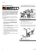
Instructions - Parts HFR Flow Meter Kits 3A1657F EN For installation and calibration of flow meters on the HFR dispensing system. For professional use only. HFR: 3000 psi (21 MPa, 207 bar) Maximum Working Pressure HFR For NVH: 2000 psi (14 MPa, 138 bar) Maximum Working Pressure Important Safety Instructions Read all warnings and instructions in the HFR, Setup-Operation and NVH, Setup-Operation manuals. Save all instructions.
Contents Contents Kits Contents . . . . . . . . . . . . . . . . . . . . . . . . . . . . . . . . . . 2 Kits . . . . . . . . . . . . . . . . . . . . . . . . . . . . . . . . . . . . . . 2 Related Manuals . . . . . . . . . . . . . . . . . . . . . . . . . . . 3 Overview . . . . . . . . . . . . . . . . . . . . . . . . . . . . . . . . . . 3 Installation . . . . . . . . . . . . . . . . . . . . . . . . . . . . . . . . 4 Calibration . . . . . . . . . . . . . . . . . . . . . . . . . . . . . . .
Related Manuals Related Manuals Overview Component manuals in English. Manuals are available at www.graco.com. Description On HFR systems, the flow meters are used only as a method of monitoring system performance, which will help with system maintenance. The ratio displayed on the ADM is a running average of the data collected. 313997 HFR Operation NOTE: The flow meters will not correct any ratio errors caused by system performance.
Installation Installation Flow Meter Electronics Kit 24J318 3. Connect CAN cable to CAN connection labeled “1” on the fluid control module. 1. Perform Shutdown procedure. See HFR or NVH operation manual for detailed instructions. 2. Use two 111800 hex head screws (supplied) to mount electronics assembly 24J318 to the bottom of the electrical enclosure.
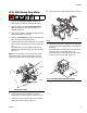
Installation HFR: 3000 Series Flow Meter 8. Route the flow meter data cable as shown in FIG. 2. 1. Perform HFR Pressure Relief Procedure. See HFR operation manual for detailed instructions. 2. Perform dispense valve Pressure Relief Procedure. See dispense valve manual, page 3, for detailed instructions. 3. Verify all air, hydraulic, and material pressures have been relieved before continuing. 4. Perform HFR Shutdown procedure. See HFR operation manual for detailed instructions. ti17013a FIG.
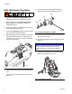
Installation HFR: 6000 Series Flow Meter 8. Connect flow meter and fittings to swivel fitting already connected to fluid manifold. See FIG. 5. 304 301 1. Perform HFR Pressure Relief Procedure. See HFR operation manual for detailed instructions. 303 2. Perform dispense valve Pressure Relief Procedure. See dispense valve manual, page 3, for detailed instructions. 302 3. Verify all air, hydraulic, and material pressures have been relieved before continuing. 4. Perform HFR Shutdown procedure.
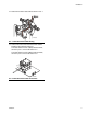
Installation 12. Route the flow meter data cable as shown in FIG. 7. ti17013a FIG. 7: Flow Meter Data Cable Routing 13. Connect the other end to the fluid control module installed in the electrical enclosure. If the data cable is for the A (Red) side flow meter, connect to port 1 on the FCM. See FIG. 2. If the data cable is for the B (Blue) side flow meter, connect to port 2 on the FCM. See FIG. 8. ti17014a FIG.
Installation NVH Flow Meters 6. If applicable, connect the A (Red) and B (Blue) return fittings. See FIG. 10. 1. Perform HFR for NVH Pressure Relief Procedure. See HFR for NVH operation manual for detailed instructions. 2. Perform dispense valve Pressure Relief Procedure. See dispense valve manual, page 3, for detailed instructions. 3. Verify all air, hydraulic, and material pressures have been relieved before continuing. 4. Perform HFR for NVH Shutdown procedure.
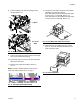
Installation 8. Connect B (Blue) flow meter and fittings to fluid manifold. See FIG. 12. 12. Connect the other end to the fluid control module installed in the electrical enclosure. If the data cable is for the A (Red) side flow meter, connect to port 1 on the FCM. See FIG. 14. If the data cable is for the B (Blue) side flow meter, connect to port 2 on the FCM. See FIG. 14. 1:1 Ratio ti17014a 24:1 or 16:1 Ratio FIG. 14: Flow Meter Data Cable Connections 13.
Installation HFR: Calibration Kit 7. Remove A (Red) and B (Blue) circulation fittings from the fluid manifold. See FIG. 16. Clean the fittings then set them aside. They will not be needed. In order to perform the calibration procedure the HFR system must have circulation lines going from the system fluid manifold back to the tanks. If the system does not have circulation lines, a calibration kit must be purchased and installed.
Installation 12. Connect the other end of the hose to the fluid manifold as shown in FIG. 18. ti17020a FIG. 18: Connect Hose to Fluid Manifold 13. Connect material return line to the open port of the tee fitting at the tank. See FIG. 17. 14. Repeat steps 9-12 for the other material side. 15. Re-install blue plastic shield that covers the center of the pumpline. 16. Re-connect material hoses to the HFR system. NOTE: Keep blank orifices and o-rings (items 7, 8, 9 in this kit) for flow meter calibration.
Calibration Calibration The following procedure describes how to adjust the mass flow rate calculated by the machine. To calculate the mass flow rate, the machine uses the chemical specific gravities entered in the Setup screens, the volumetric flow measured by the flow meters, and the K-Factor inputs for each chemical. Using a Blocked Orifice The flow meters do not require regular calibration.
Calibration Parts and Tools Required GX-7DI Only Fusion, EP, Probler P2 • 5/16 Nut Driver • Scale • Adjustable Wrench • Two containers to catch dispensed material • Scale • Adjustable wrench • Two large containers with lids (a hole will need to be cut into the lid slightly larger than the spray nozzle. Using a 5 gallon pail and removing the pull out spout from the bung is recommended).
Calibration Calibrate Material Weight Measurement For S-Head and L-Head Dispense Valves Only -a. Remove the four hex bolts on the chemical side not being calibrated. For more detailed instructions regarding steps in this procedure, see Related Manuals listed on page 3. 1. If not already completed, install the flow meters. See Installation starting on page 12. 2.
Calibration For Probler P2 Gun Only -a. Disconnect both material lines at the gun. See gun manual listed on page 3. b. c. Attach material lines to fluid manifold (1) included in calibration kit 24J326. See FIG. 19. Place o-rings (2) in correct location then attach fluid manifold to the base (3) of the calibration kit. For L-Head, S-Head, GX-7 DI, and GX-16 Dispense Valves Only -• If calibrating the A (Red) side, close the B (Blue) valve on the fluid manifold. Make sure the A (Red) valve is open.
Calibration 11. Press lines. to dispense a shot to prime the material 21. Press to exit the System screen then use the arrow keys to navigate to the Calibration screen. 12. Remove container from below the dispense valve. 13. Press repeatedly to select Standby mode. 14. Press to access the Setup screens. 15. Use the arrow keys to navigate to System screen #3. 22. Press to access the weight calibration and material specific gravity screen. 23.
Calibration 25. Press screen. to go to the flow meter calibration All Assemblies -28. Press stop. to begin dispensing then press again to NOTE: For better results, it is recommended to dispense for a minimum of 10 seconds. 29. Weigh the container(s) and record the weight(s). Subtract the weight of each bucket measured before the shot to obtain the weight of each material dispensed. 30.
Calibration 38. Prepare dispense valve: For GX7-DI Dispense Valves -a. Close off material flow to the dispense head for BOTH chemicals. Turn the valve on the coupling block manifold fully clockwise until tight. b. Remove and clean the mixing module retainer. c. Remove and clean the mix module. The dispense valve can be manually cycled open and closed by pressing the dispense valve button on the Maintenance screen. Cycle open and closed once to pull the module partially off of the valve rod.
Flow Meter Connector Pinout Flow Meter Connector Pinout The system utilizes a 5-pin CAN connection for communication with the flow meter. If a non-Graco flow meter is used the flow meter signal must be converted to the following 5-pin connection. NOTE: The connection shown is the FCM connector, not the CAN cable pins. 1 1 +10-30 VDC Supply 2 Signal out 3 Ground 4 Not Used 5 Not Used 2 5 4 3 FIG.
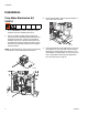
Parts Parts HFR and NVH: Flow Meter Electronics Kit, 24J318 103 108 107 102 105 106 111 112 104 109 110 ti17023a 101 Ref 101 102 103 104 105 106 107 108 109 110 111 112 113 20 Part 24J328 289697 289696 24H240 102063 114993 102598 277674 100985 100015 121002 Description Qty PLATE, mounting, electronics 1 MODULE, base 1 MODULE, FCM 1 HARNESS, wire, ground, term, 9 in.
Parts HFR: 3000 Series Flow Meter Kits 203 202 201 206 205 204 ti17024a Ref 201 202 203 204 205 206 Part 258718 239716 244292 262205 262206 123596 123597 125103 3A1657F Description METER, gear, S3000 METER, gear, G3000 METER, gear, G3000HR FITTING, swivel, npt x JIC FITTING, swivel, 1/4 npt x 6 JIC ADAPTER, 5/16 JIC x 1/4 npt ADAPTER, 3/8 JIC x 1/4 npt HARNESS, M12 x cir, 5-pin x 3-pin, male x female 24J319, S3000 1 Quantity 24J320, 24J321, G3000 G3000HR 1 1 1 1 1 1 1 1 1 1 1 1 1 1 1 1 1 21
Parts HFR: 6000 Series Flow Meter Kits 304 301 303 302 305 Ref 301 302 303 304 305 22 Part 246190 246652 114190 114496 502033 123657 Description METER, helical gear, HG6000 METER, helical gear, HG6000HR SWIVEL, stainless steel, 1/2 npt FITTING, nipple FITTING, bushing, pipe CABLE, 5-pin, male / female, 3.
Parts NVH: 24:1 and 16:1 Flow Meter Kits 605 614 606 601 615 613 607 610 611 609 613 608 602 612 Quantity Ref 601 602 603 604 605 606 607 608 609 610 611 612 613 614 615 616 617 Part 246652 289814 123657 125103 156877 123980 124286 123597 124814 114190 124586 124152 16W140 16W141 112569 257700 16G407 3A1657F Description METER, heli gear, high resolution METER, gear, assembly, G3000HR CABLE, 5pin, male/female, 3.
Parts NVH: 1:1 Flow Meter Kits 703 710 704 701 711 703 704 705 707 709 706 708 Ref 701 702 703 704 Part 246652 123657 156877 123980 Description METER, heli gear, high resolution CABLE, 5pin, male/female, 3.5meter FITTING, nipple, long FITTING, swivel, 3/4x1/2, male x female, sst, 3.
Parts HFR: Flow Meter Calibration Kits for Hydraulic Dispense Valves 403 401 402 404 406 ti17025a 405 Ref 401 Part 262184 402 403 404 117506 122311 124281 405 406 407* 103475 158491 M0934A-4 24A036 408* 409* * 257700 285967 122679 Description HOSE, b, 10 ft., 3/8 in.
Parts Flow Meter Calibration Kit for Probler P2 Gun, 24J326 Ratio Check Kit for Fusion Gun, 24F227 Fluid manifold shown for reference only 501 502 503 ti17026a ti17021a See instruction manual 3A0861 for parts information. Ref 501 502 503 Part 246012 117520 24F227 Description MANIFOLD, fluid O-RING KIT, ratio check Qty 1 2 1 Ratio Check Adapters for MD2 Valve ti12392a1 255247 shown Use ratio check adapter 255247 for 1:1 MD2 valves. Use 255245 for 10:1 MD2 valves.
Technical Data Technical Data See Technical Data in the HFR or HFR for NVH system manuals for more information. Wetted Parts . . . . . . . . . . . . . . . . . . . . . . . . . . . . . . . . .
Graco Standard Warranty Graco warrants all equipment referenced in this document which is manufactured by Graco and bearing its name to be free from defects in material and workmanship on the date of sale to the original purchaser for use. With the exception of any special, extended, or limited warranty published by Graco, Graco will, for a period of twelve months from the date of sale, repair or replace any part of the equipment determined by Graco to be defective.