
User's Manual

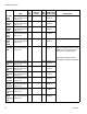
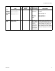

Available Internal Data
20 3A1704G
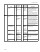
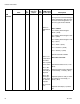
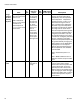
Change
Tempera-
ture Con-
ditioning
Set point
Depending on system
setup the units can be
read in C or F
LSW = Desired set
point in 0.1°C for stan-
dard HFR units.
Desired setpoint in
0.1 °C / 0.1°F for recir-
culation units.
25-26 The tempera-
ture set points
are limited by
the tempera-
ture high and
low alarm val-
ues. There
must be a dif-
ference of at
least 10
between the
new set point
and the alarm
values or the
new set point
will be ignored.
-- -- The value outputted to the CGM
must be an integer and must be
multiplied by 10 for the requested
zone temperature. Temperature
input into the PLC == xxx.x F or C
and must be changed to xxxx C
prior to sending to the CGM (stan-
dard HFR only). The temperature
set points are limited by the temper-
ature high and low alarm values.
The alarm setpoints must be greater
than 10 degrees (standard HFR) or
2 degrees (recirculation unit) from
the requested setpoint. If the alarm
is closer than 10 degrees (standard
HFR) or 2 degrees (recirculation
unit) then the requested setpoint will
be ignored. Manually changing the
alarm setpoints on the ADM will be
required prior to a new setpoint
change. See Output Bytes 63 thru
78 for temperature zone feedback
from the CGM.
LSW = Desired Set point in 0.1°
units
LSW + MSW combined to form a
DINT from the PLC output to CGM
input.
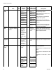
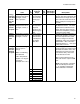
System
Power
System Power 27 Toggles Sys-
tem Power on
change.
-- -- System power is ON when the ADM
is in any active mode. System
power is OFF when the power LED
is in the yellow state. To turn the
System power ON or OFF, write a
different value to the System Power
byte. Changing the value will toggle
the state from ON to OFF or OFF to
ON. See Out Byte 84 for System
Power Status
Units
In
Byte
CGM Input
from PLC
Output
Out
Byte
CGM Output
to PLC Input Descriptions