
User's Manual

Available Internal Data
22 3A1704G
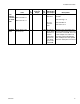
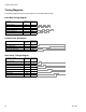
Timing Diagrams
The following diagrams show the signal sequence of the CGM communication.
Heart Beat Timing Diagram
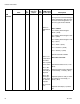
System Power Bit Diagram
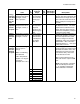
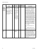
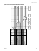
Shot Setup - Change Diagram
Heart Beat CGM Input
Bytes /Bit
CGM Output
Bytes /Bit
CGM HB - Normal
PLC HB - Normal
CGM HB - No HB
PLC HB - Cycle Hi / Lo
I/O
I/O
I/O
I/O
System Power Bit CGM Input
Bytes /Bit
CGM Output
Bytes /Bit
Set CGM Control
Verify CGM Control
Verify System Power ON
2/7
2/7
27
84/0
System Power ON
Shot Setup - Change CGM Input
Bytes /Bit
CGM Output
Bytes /Bit
Select Shot Mode
Verify Shot Mode
Verify Shot Number
Set Flow Rate
3
Select Shot Number
Set Shot Size
Verify Flow Rate
Verify Shot Size
3
4
4
13-16
13-16
17-20
19-22