Instructions-Parts Informer® Fluid Monitoring 3A2040E Kits EN Use to monitor flow rate and track material use. For professional use only. Important Safety Instructions Read all warnings and instructions in this manual. Save these instructions. See the G3000 meter manual (308778) or Coriolis meter manual (313599) for flow meter maximum working pressure. See page 3 for kit information, including approvals. PROVEN QUALITY. LEADING TECHNOLOGY.
Contents Informer Models and Kits .................................... 3 Warnings ........................................................... 5 Installation.......................................................... 8 Overview ..................................................... 8 Non-Hazardous Locations ............................ 9 Hazardous Locations.................................... 10 Grounding ................................................... 12 Cable Connections..................................
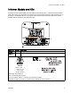
Informer Models and Kits Informer Models and Kits All Display Control Modules (DCM) are base model number 24L096 (Ref. 1). Models 24L096 and 24N671 (DCM with bracket) are not available for separate sale. See approval information in Manual 332013 and on this page. The small label (Ref. 2) on the back of the Informer module shows the Informer Kit number. Available kits are described in the tables that follow. Model No. Series Description 24L096 A Display Control Module (DCM), with no software loaded.
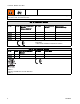
Informer Models and Kits Informer systems are not approved for use in hazardous locations unless all accessories and all wiring meet local, state, and national codes. Kits for Hazardous Locations Kit No. Series Informer Module with Bracket (Manual 332013)* No Power 24L073 A ✔ ✔ 24L074 A ✔ ✔ 24L077 A ✔ ✔ 24L078 A ✔ ✔ AC Power with Barrier** G3000 Meter (Manual 308778)* ✔ ✔ * See component manuals for additional approval information. ** Must not be installed in Hazardous Location.
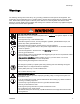
Warnings Warnings The following warnings are for the setup, use, grounding, maintenance and repair of this equipment. The exclamation point symbol alerts you to a general warning and the hazard symbol refers to procedure-specific risks. When these symbols appear in the body of this manual or on warning labels refer back to these Warnings. Product-specific hazard symbols and warnings not covered in this section may appear throughout the body of this manual where applicable.
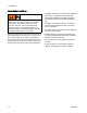
Warnings INTRINSIC SAFETY WARNING Intrinsically safe equipment that is installed improperly or connected to non-intrinsically safe equipment will create a hazardous condition and can cause fire, explosion, or electric shock. Follow local regulations and the following safety requirements.
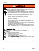
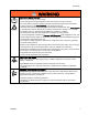
Warnings WARNING EQUIPMENT MISUSE HAZARD Misuse can cause death or serious injury. • Do not operate the unit when fatigued or under the influence of drugs or alcohol. • Do not exceed the maximum working pressure or temperature rating of the lowest rated system component. See Technical Data in all equipment manuals. • Use fluids and solvents that are compatible with equipment wetted parts. See Technical Data in all equipment manuals. Read fluid and solvent manufacturer’s warnings.
Installation Installation Overview The purpose of the Informer Display Control Module is to collect and display fluid data. The Informer connects the output signal from a meter to a display module that performs the following functions: • Shows real-time fluid flow rate. • Displays a resettable batch totalizer. • Monitors and reports overall fluid use. The Informer is available in configurations for Hazardous Location or Non-Hazardous Location installation.
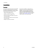
Installation Non-Hazardous Locations NOTE: Non-IS Informer modules are shipped with a 120 VAC power cord (E). Users in areas with another standard voltage must provide a power supply cord with an IEC 320–C13 female connector. See Technical Data, page 41, for power requirements.. or generates more than 250 vrms or d.c. unless it has been determined that the voltage has been adequately isolated.
Installation Hazardous Locations Do not substitute or modify system components as this may impair intrinsic safety. For installation, maintenance, or operation instructions, read instruction manuals. Do not install equipment approved only for non-hazardous location in a hazardous location. See the identification label for the intrinsic safety rating for your model. Intrinsically safe equipment should not be used with a power supply that has no barrier. Do not move units from a non-IS setup to an IS setup.
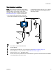
Installation Nonhazardous Location Hazardous Location KEY: A Flow Meter, 1/4 npt female inlet/outlet. B Informer Module C Power Supply with Barrier D Meter Cable (50 ft., 15 m), to terminal 4. See Cable Connections, page 12. E Power Cord (not supplied) F Power Cable (50 ft., 15 m), to terminal 3. See Cable Connections, page 12. M Ground wire and clamp. PN 244524 is included with kits to ground the Informer Module. PN 238909 is sold separately to ground the meter or power supply.
Installation Grounding 1. Power Supply 16M167: Connect the ground wire from the power supply to a true earth ground. The equipment must be grounded to reduce the risk of static sparking and electric shock. Electric or static sparking can cause fumes to ignite or explode. Improper grounding can cause electric shock. Grounding provides an escape wire for the electric current. NOTE: The Informer does not provide 500 VAC isolation through the coupling nuts on the enclosure.
Installation Electrical Connections Install per Graco Control Drawing 16M169, in Manual 332013. See also Figure 1. 1. Connect main power supply cord (E, not supplied) through strain relief to terminals L and N on the power supply unit. Note: Use either strain relief (5) or (6), depending on the size of the cord. Power Cable Leads Barrier Connection Brown (power) Connector 1 Blue (common) Connector 2 Glossy Black (ground) and Black (drain) connect to ground block. 2.
Installation Typical Installation Non-Hazardous Location Hazardous Location 14 3A2040E
Installation A1 and A2 Flow Meters Supplied in some kits. See Parts, page 31. B1 and B2 Informer Module Supplied. C Power Supply and Barrier Supplied in Hazardous Location Kits D Meter Cable (50 ft., 15 m) Supplied. E Power Cord (10 ft., 3 m) Supplied in Non-Hazardous Location Kits F Power Cable (50 ft., 15 m) Supplied G Fiber Optic Cable Accessory. See Accessories, page 33. H Serial Cable Accessory. See Accessories, page 33. J Advanced Web Interface Accessory.
Operation Operation 3. Follow the Pressure Relief Procedure for your fluid system dispensing device. Flow Meter Operation Pressure Relief Procedure Follow the Pressure Relief Procedure whenever you see this symbol. This equipment stays pressurized until pressure is manually relieved.
Operation Meter Calibration NOTE: See Setup Screen 4 for further screen information, if needed. When to Calibrate • The first time the system is operated. • Whenever new materials are used in the system, especially if the materials have viscosities that differ significantly. • As part of regular maintenance to retain meter accuracy. • Whenever a flow meter is serviced or replaced.
Operation 5. Dispense about 300–500 cc of material into a graduated cylinder. The amount the system measures will display in the measured volume field 6. Press 7. Press . to end the calibration. to get to the dispensed volume field , then press to enter the field. Enter the amount of material in the cylinder. Update Software Software updates are installed using a software token (PN 16P468), which is sent automatically when a new version of the software is released.
Operation Replace Battery Replace the battery only if the clock stops functioning after disconnecting power or a power failure. Sparking can occur when changing the battery. Replace the battery only in a non-hazardous location, away from flammable fluids or fumes. NOTICE To avoid damage to the circuit board, wear Part No. 112190 grounding strap, and ground appropriately. 5. Use a flathead screwdriver to pry out the old battery.
Display Module Display Module Display Information The Display Module provides the interface for users to enter selections and view information related to setup and operation. The screen backlight is factory set to remain on, even without screen activity. See Setup Screen 3 to set the backlight timer to your preference. Press any key to restore. Keys are used to input numerical data, enter setup screens, navigate within a screen, scroll through screens, and select setup values.
Display Module Icons As you move through the Informer screens, you will notice that most information is communicated using icons rather than words to simplify global communication. The detailed screen descriptions in Run Screens, page 23, and Setup Screens, page 25, explain what each icon represents. Icon reference tables also are provided, on this page and the next. Softkeys are membrane buttons whose function correlates with the screen content to the immediate left of the button.
Display Module Screen Icons Screen Icons Set Serial Port Parity Screen number. The arrows indicate more screens are available to view. Lock icon indicates the unit is in Setup mode.
Run Screens Run Screens When in Run Mode, the Informer displays the current flow rate and batch total on Screen 1. Screen 2 displays the grand total for the flow meter to which it is connected. Screens 3–6 display a log of the last 20 alarms. Run Screen 2 Use this screen to view the grand total flow for the system. The grand total cannot be reset. Run Screen 1 Use this screen to view the current batch total and flow rate, or to reset the batch totalizer to 0.
Password Screen Run Screens 3 — 6 Use Screens 3 — 6 to view the log of recent alarms. Password Screen If a password has been set, the Password Screen is pressed from any Run screen. displays when Enter password to enable entry to the Setup screens. Set the password to 0000 to disable password protection. See Setup Screen 7 to set or change the password. Figure 4 Run Screen 3 Key Date on which the Deviation or Advisory Alarm occurred. Time at which the Deviation or Advisory Alarm occurred.
Setup Screens Setup Screens The Setup Mode is used to set up a password (if desired) and to set parameters for monitoring fluid flow with the Informer. See Screen Navigation and Editing, page 20, for information on how to make selections and enter data. Setup Screen 1 Use this screen to view and reset the maintenance totalizer, set the maintenance target value, and set the batch and grand totalizer units shown on the Run Screens. Maintenance totalizer units, shown on this Setup Screen, are always cc.
Setup Screens Setup Screen 2 Setup Screen 3 Use this screen to set your flow rate maximum and minimum values and to select units for flow rate. Use this screen to set your alarm preferences. Select to enable the alarm, or leave the box empty to disable the alarm. Figure 7 Setup Screen 2 Key Enter the screen to set or change preferences. Press to activate a field for editing or to accept the highlighted selection on a dropdown menu. Move to the right when editing number fields.
Setup Screens Setup Screen 4 Setup Screen 5 Use this screen to calibrate your meter and to view or set your meter k-factor. See Meter Calibration, page 17, for procedure. Use this screen to set your modbus preferences for ports 1 and 2. Note that ports 5 and 6 are used as modbus master devices for connecting to other Informer (or ProCrontol 1KE) modules. Figure 9 Setup Screen 4 Figure 10 Setup Screen 5 Key Enter the screen to set or change preferences.
Setup Screens Setup Screen 6 Setup Screen 7 Use this screen to set your date format, date, and time. Use this screen to enter a password that will be required to access the Setup screens. This screen also displays the software version. Figure 11 Setup Screen 6 Figure 12 Setup Screen 7 Key Enter the screen to set or change preferences. Press to activate a field for editing or to accept the highlighted selection on a dropdown menu. Move to the right when editing number fields.
Deviations and Advisories Deviations and Advisories There are two types of errors that can occur. Errors are indicated on the display. Deviations, indicated by not immediately. , require attention, but Alarm Log Logic: If Alarm Auto Clear is enabled, the system will not log the same alarm twice. For example, if the system fluctuates between low flow (F2) and acceptable flow, the system will log this error only once, to keep the log from filling up before the operator corrects the condition.
Troubleshooting Troubleshooting Problem Cause Solution Power is not on. Turn power supply on. Loose or disconnected power cable. Tighten or connect cable. Informer has power but does not function. Hardware failure. Replace Informer. Flow Rate reads 0 when fluid is flowing. Loose or disconnected flow meter cable. Check the digital input/output cable going to/from the meter. Inaccurate flow reading Faulty flow meter sensor or meter. Replace sensor or meter. Meter needs calibration.
Parts Parts Kits for Hazardous Location, 24L074, 24L077, and 24L078 Nonhazardous Location Hazardous Location Kits 24L074, 24L077, and 24L078 Ref. Part Description 1 24L073 MODULE, Informer, includes 1a-1c 1a N/A MODULE, Informer, with software 1b 277853 BRACKET 1c▲ 16P265 LABEL, warning, not shown 4 289813 METER, G3000 5 16V074 7 16M167 8 16K509 9 244524 CABLE, intrinsically safe*, meter, 16 m (52.5 ft.) POWER SUPPLY, 90–264 VAC input, 15 VDC output. See Manual 332196.
Parts Kits for Non-Hazardous Location, 24L075 and 24L076 Part Description 1 24L073 MODULE, Informer, includes 1a-1c 1a N/A MODULE, Informer, with software 1b 277853 BRACKET 1c▲ 16P265 LABEL, warning, not shown 4 Ref. 289813 METER, G3000 5 16K483 CABLE, meter,16 M (52.5 ft.
Accessories Accessories Not all accessories and kits are approved for use in hazardous locations. Refer to the specific accessory and kit manuals for approval details. Accessories for Hazardous Locations Part No. Description 16K615 Power Cable, 100 ft (30 m), for power supply. 16K509 Power Cable, 50 ft (15 m), for power supply. 16M172 Fiber Optic Cable, 50 ft (15 m). 16M173 Fiber Optic Cable, 100 ft (30 m). 289814 G3000HR Meter, Positive displacement, gear flow meter, 0.01 to 0.
Mounting Dimensions Mounting Dimensions Figure 13 Power Supply Figure 14 Informer Module B Overall Height in. (mm) Overall Depth in. (mm) Mounting Dimensions Width (C) x Height (D) in. (mm) Power Supply 16M167 16.6 (420.9) 8.7 (221.2) 4.5 (114.8) 15.1 x 6.7 (382.8 x 170.2)) 0.31 (7.9) Informer 7.2 (183) 6.0 (152) 2.8 (71) 2.5 x 3.0 (64 x 76) 0.28 (7) Component 34 E Mounting Hole Size in. (mm) A Overall Width in.
Appendix A - Modbus Variable Map Appendix A - Modbus Variable Map Table 1 Device Identification Registers Description Size Read Only Informer Modbus Register 401040 Software Version Major 32 Bit Read Only 401042 Software Version Minor 32 Bit Read Only 401044 Software Version Build 32 Bit Read Only 401072 Serial Number String - Bytes 0-3 32 Bit String, 4 Bytes Read Only 401074 Serial Number String - Bytes 4-7 32 Bit String, 4 Bytes Read Only 401076 Serial Number String - Bytes 8-11
Appendix A - Modbus Variable Map Read/Write 402017 Read/Write 402019 Calibration, Measured Volume Calibration, Actual Dispensed Volume 32 Bit pulses 0 32-bit 32 Bit cc 0 32-bit Table 3 Setup Registers Register Informer Description Permissions Modbus Register Read/Write 403000 Communication, Modbus Mode Size Units Low High Limit Limit 16 Bit 0=off, 1=on 0 1 Read/Write 403001 Communication, Modbus Address 32 Bit 1-247 1 247 Read/Write 403003 Communication, Modbus Baud Rate 16 Bit
Appendix B - Advanced Web Interface Appendix B - Advanced Web Interface Overview The Advanced Web Interface (AWI) is Graco PN 15V337. It is an accessory that works with many Graco devices to enable communication with a PC via ethernet. The kit includes Manual 332459, which contains installation and setup information common to all devices. It includes sections on how to configure your computer, initialize the system, configure the main system settings, and set up your network.
Appendix B - Advanced Web Interface Monitor Tab Use this tab to monitor the current device in real time. The only change that can be made on this tab is to reset the batch total. Click Reset to change the batch total immediately to zero.
Appendix B - Advanced Web Interface Setup Tab Click on Setup. Use this tab to view or change your Informer settings. For items with a field, type the desired number in the field and press Enter on your keyboard. The change takes place when you press Target In this screen section, view or adjust your maintenance target, maximum flow rate target, and minimum flow rate target. Type the desired number in the field. 3A2040E Enter. For drop-down menus, click on the desired option. The change is immediate.
Appendix B - Advanced Web Interface K-Factor In this screen section, view or adjust the k-factor for the system’s meter. See Meter Calibration, page 17. Modbus In this screen section, view the modbus mode, address, baud rate, and parity. Modbus information must be adjusted on the Informer. If you were to adjust it on your PC, the change would cause a disruption in your connection.
Technical Data Technical Data Informer Metric US Power In Requirements: Voltage: 90–264 VAC Frequency: 50-60 Hz Phase: 1 Amps: 1.25A maximum Power Out Requirements: Power Supply 16V680 15 VDC, 1.
Graco Standard Warranty Graco warrants all equipment referenced in this document which is manufactured by Graco and bearing its name to be free from defects in material and workmanship on the date of sale to the original purchaser for use. With the exception of any special, extended, or limited warranty published by Graco, Graco will, for a period of twelve months from the date of sale, repair or replace any part of the equipment determined by Graco to be defective.