Instructions-Parts E-Flo® DC 4–Ball Piston Pumps Electric drive piston pumps for low to medium volume paint circulation applications. For professional use only. Important Safety Instructions Read all warnings and instructions in this manual. Save these instructions. See Technical Data, page 29, for Maximum Working Pressure. See page 3 for model part numbers and approvals information. PROVEN QUALITY. LEADING TECHNOLOGY.
Contents Models............................................................... 3 Related Manuals ................................................ 3 Warnings ........................................................... 4 Installation.......................................................... 8 Location ...................................................... 8 Mount the Pump .......................................... 8 Power Supply Requirements......................... 8 Connect the Power Supply ................
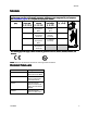
Models Models The part number for your equipment is printed on the equipment identification label (L). The part number includes digits from each of the following categories, depending on the configuration of your equipment. Matrix,, page 20 for a complete list of pump part numbers.
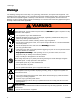
Warnings Warnings The following warnings are for the setup, use, grounding, maintenance, and repair of this equipment. The exclamation point symbol alerts you to a general warning and the hazard symbols refer to procedure-specific risks. When these symbols appear in the body of this manual or on warning labels, refer back to these Warnings. Product-specific hazard symbols and warnings not covered in this section may appear throughout the body of this manual where applicable.
Warnings WARNING MOVING PARTS HAZARD Moving parts can pinch, cut or amputate fingers and other body parts. • Keep clear of moving parts. • Do not operate equipment with protective guards or covers removed. • Pressurized equipment can start without warning. Before checking, moving, or servicing equipment, follow the Pressure Relief Procedure and disconnect all power sources.
Warnings WARNING EQUIPMENT MISUSE HAZARD Misuse can cause death or serious injury. • Do not operate the unit when fatigued or under the influence of drugs or alcohol. • Do not exceed the maximum working pressure or temperature rating of the lowest rated system component. See Technical Data in all equipment manuals. • Use fluids and solvents that are compatible with equipment wetted parts. See Technical Data in all equipment manuals. Read fluid and solvent manufacturer’s warnings.
Notes Notes 3A2096D 7
Installation Installation Power Supply Requirements Installation of this equipment involves potentially hazardous procedures. Only trained and qualified personnel who have read and who understand the information in this manual should install this equipment. Location When selecting the location for the equipment, keep the following in mind: • There must be sufficient space on all sides of the equipment for installation, operator access, maintenance, and air circulation.
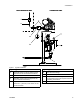
Installation NON--HAZARDOUS AREA NON HAZARDOUS AREA Figure 1 Typical Installation Key for Fig. 1 Key for Fig. 1 A Electrical Supply (must be sealed conduit approved for use in hazardous locations) E Fluid Pressure Gauge F Fluid Shutoff Valve B Fused Safety Switch, with lock G C Start/Stop Control (must be approved for use in hazardous locations) Pump Ground Wire. Two ground terminals are provided if local code requires redundant grounding connections. D Explosion Proof Conduit Seal.
Installation Connect the Power Supply Improper wiring may cause electric shock or other serious injury if work is not performed properly. Have a qualified electrician perform any electrical work. Be sure your installation complies with all National, State and Local safety and fire codes. 3. Open the electrical compartment (S) on the motor. 4. Bring the power wires into the electrical compartment through the 3/4–14 npt(f) inlet port. Connect the wires to the terminals, as shown.
Installation Grounding This equipment must be grounded to reduce the risk of static sparking and electric shock. Electric or static sparking can cause fumes to ignite or explode. Improper grounding can cause electric shock. Grounding provides an escape wire for the electric current. 1. Pump: See Fig. 4. Loosen the ground screw and attach a ground wire. Tighten the ground screw securely. Connect the other end of the ground wire to a true earth ground.
Installation Fluid Line Accessories Install the following accessories in the order shown in Fig. 1, using adapters as necessary. All fluid lines and accessories must be rated to the maximum working pressure of 400 psi (2.8 MPa, 28.0 bar). • Fluid drain valve (D): required in your system, to relieve fluid pressure in the hose and circulation system. • Fluid pressure gauge (E): for more precise adjustment of the fluid pressure. • Fluid shutoff valve (F): shuts off fluid flow.
Operation Operation Startup To operate the pump, follow the Startup instructions for the Basic or Advanced motor in the Motor manual. The Advanced E-Flo DC motors require installation of the 24P822 Control Module Accessory Kit to provide the interface for users to enter selections and view information related to setup and operation. See the Control Module Accessory Kit manual for installation and operation information.
Maintenance Maintenance Preventive Maintenance Schedule Check Oil Level The operating conditions of your particular system determine how often maintenance is required. Establish a preventive maintenance schedule by recording when and what kind of maintenance is needed, and then determine a regular schedule for checking your system. See Fig. 7. Check the oil level in the sight glass (K). The oil level should be near the halfway point of the sight glass when the unit is not running.
Troubleshooting Troubleshooting NOTE: Check all possible remedies before disassembling the pump. NOTE: The LED on the motor will blink if an error is detected. See Error Code Troubleshooting in the motor manual for further information. Problem Cause Solution Pump output low on both strokes. Inadequate power supply. See Power Supply Requirements, page 8 . Exhausted fluid supply. Refill and reprime pump. Clogged fluid outlet line, valves, etc. Clear. Worn piston packing. Replace.
Repair Repair Disassembly Reassembly NOTE: If the coupling adapter (9) and tie rods (6) have been disassembled from the motor, see Reassemble the Coupling Adapter and Tie Rods to the Motor, page 17. 1. Stop the pump at the bottom of its stroke. 2. Relieve the pressure. See the Pressure Relief Procedure, page 13. 3. Disconnect the hoses from the lower and plug the ends to prevent fluid contamination. 4.
Repair Reassemble the Coupling Adapter and Tie Rods to the Motor NOTE: Use this procedure only if the coupling adapter (9) and tie rods (6) have been disassembled from the motor, to ensure proper alignment of the motor shaft to the piston rod (R). 2. Screw the coupling adapter (9) into the motor shaft and torque to 90–100 ft-lb (122–135 N•m). 3. Reassemble the pump to the motor, as explained in Reassembly, page 16. 1. See Fig. 7.
Parts Parts Pump Assembly See Models, page 3 for an explanation of the pump part number.
Parts Part Description KIT, mounting bracket, pump; includes items 4 and 5; see manual 311619 STAND, floor Qty 1 Ref 1 See Pump Matrix, page 20 2 See Pump Matrix, page 20 3 See Pump Matrix, page 20 3a▲ 16M130 3b 16W645 4 5 See Pump Matrix, page 20 See Pump Matrix, page 20 6 7 8 15G924 See Pump Matrix, page 20 108683 NUT, lock, hex 3 9 15H369 ADAPTER 1 10 184128 COLLAR, coupling NUT, coupling 2 1 KIT, shield, coupler (includes 2 pieces) 1 11 184059 12 24F251 MOTOR; Basic or A
Parts Pump Matrix Pump Part No.
Parts Pump Part No.
Dimensions Dimensions A B C D 58.00 in. (1473 mm) 17.00 in. (432 mm) 45.50 in. (1156 mm) 19.88 in.
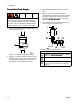
Mounting Hole Patterns Mounting Hole Patterns Floor Stand Dimension Measurement A 19.88 in. (505 mm) B 14.50 in. (368 mm) C 16.88 in. (429 mm) D 17.00 in.
Mounting Hole Patterns Pump Bracket Dimension Measurement A 17.8 in. (451 mm) B 14.5 in. (368 mm) C 12.4 in. (314 mm) D 9.0 in. (229 mm) E 5.4 in. (137 mm) F 7.4 in. (187 mm) G 5.3 in. (133 mm) H 2.0 in. (51 mm) J 1.0 in. (25 mm) K 1.6 in. (41 mm) L 2.7 in. (69 mm) M 4.4 in. (112 mm) N Four 0.562 in. (14 mm) diameter holes for mounting to stand P Four 0.438 in.
Performance Charts Performance Charts To find the fluid pressure (psi/bar/MPa) at a specific fluid flow (gpm/lpm) and percentage of maximum force: 1. Locate the desired fluid flow in the scale at the bottom of the chart. 2. Follow the vertical line up to the intersection with the selected percentage of maximum force (see the Key below). 3. Follow left to the vertical scale to read the fluid outlet pressure.
Performance Charts Table 3 . Models EC21xx and EC22xx (1000 cc lower, 1 HP motor, 1400 lb maximum force) CYCLES PER MINUTE FLUID PRESSURE: psi (bar, MPa) NOTE: The shaded area within the table shows the recommended range for continuous duty circulation applications. FLUID FLOW: gpm (lpm) Table 4 .
Performance Charts Table 5 . Models EC33xx and EC34xx (1500 cc lower, 2 HP motor, 2800 lb maximum force) CYCLES PER MINUTE FLUID PRESSURE: psi (bar, MPa) NOTE: The shaded area within the table shows the recommended range for continuous duty circulation applications. FLUID FLOW: gpm (lpm) Table 6 .
Notes Notes 28 3A2096D
Technical Data Technical Data U.S. Metric Models EC11xx and EC12xx 300 psi 2.07 MPa, 20.7 bar Models EC21xx and EC22xx 200 psi 1.38 MPa, 13.8 bar Models EC23xx and EC24xx 400 psi 2.76 MPa, 27.6 bar Models EC33xx and EC34xx 300 psi 2.07 MPa, 20.7 bar Models EC43xx and EC44xx 220 psi 1.52 MPa, 15.
Graco Standard Warranty Graco warrants all equipment referenced in this document which is manufactured by Graco and bearing its name to be free from defects in material and workmanship on the date of sale to the original purchaser for use. With the exception of any special, extended, or limited warranty published by Graco, Graco will, for a period of twelve months from the date of sale, repair or replace any part of the equipment determined by Graco to be defective.