Instructions Modular Box Lubricator 3A2100C EN Fluid container used with GBL7500 Suction Fed, Gravity Fed or Pressure Fed Box Lubricator Pumps used for dispensing non-corrosive and non-abrasive oils and lubricants. For professional use only. See Technical Data, page 13 for maximum outlet pressures per pump station. Important Safety Instructions Read all warnings and instructions in this manual and your pump instruction manual. Save all instructions. See page 2 for part number information.
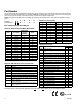
Part Number Use the Part Number Key provided below to identify each system component. The Code for each Option that makes up the Part Number are provided in the tables below. For example, MBB1DE is a Modular Box; 6 pint reservoir, (maximum of 3 pumping stations and no motor mount base); 3/16 suction fed pump; 3 pumps; and a direct end rotary drive. NOTE: Some pump configurations are not available. Contact Graco Customer Service or your local Graco distributor for assistance.
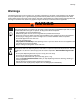
Warnings Warnings The following warnings are for the setup, use, grounding, maintenance, and repair of this equipment. The exclamation point symbol alerts you to a general warning and the hazard symbols refer to procedure-specific risks. When these symbols appear in the body of this manual, refer back to these Warnings. Product-specific hazard symbols and warnings not covered in this section may appear throughout the body of this manual where applicable.
Warnings WARNING EQUIPMENT MISUSE HAZARD Misuse can cause death or serious injury. • Do not operate the unit when fatigued or under the influence of drugs or alcohol. • Do not exceed the maximum working pressure or temperature rating of the lowest rated system component. See Technical Data in all equipment manuals. • Use fluids and solvents that are compatible with equipment wetted parts. See Technical Data in all equipment manuals. Read fluid and solvent manufacturer’s warnings.
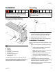
Installation Installation Grounding Modular box lubricators are not approved for use in hazardous locations or explosive atmospheres unless all accessories, components and wiring meet all local and national codes. The equipment must be grounded to reduce the risk of static sparking. Static sparking can cause fumes to ignite or explode. Grounding provides an escape wire for the electric current. Component Identification a b D H J B FIG. 2 ti17757 1. Loosen grounding screw (a) (FIG.
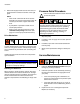
Installation 4. Remove fill cap (B) and fill reservoir with clean, filtered fluid until it reaches the full line on the sight glass. NOTE: • Filter oil with a minimum 25 micron strainer. Depending on machine requirements it may be necessary to maintain a higher cleanliness level. • A pump blank is provided to install over all unused pump stations. • Refer to pump instruction manual for pump installation and priming instructions. (See page 12 for Graco pump model information.
Installation 4. Clean lubricator periodically to eliminate contamination that may have occurred in the oil. To accomplish this: a. Drain reservoir by removing drain plug (C) (FIG. 1). Dispose of oil according to all applicable safety regulations. b. Remove all pumping units. c. Clean the pumps and reservoir by brushing loose all foreign matter, dipping in solvent and blowing dry with compressed air. d. Replace pumping units. Torque mounting screws (J) to 110 in. lbs + 10 in. lbs. (12.43 N.m + 1.13 N.
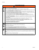
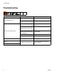
Troubleshooting Troubleshooting Problem Solution Low oil level in reservoir Add oil. See Refilling the Reservoir, page 6. Pump issue Refer to the Troubleshooting Section of your pump instruction manual. Low oil level in reservoir Add oil. See Refilling the Reservoir, page 6. Camshaft not rotating because rotatory power source is defective Replace rotary power source. Camshaft not rotating because rotatory power source connection is defective Fix rotary power source connection to lubricator box.
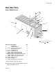
Bare Box Parts Bare Box Parts Model: MBD0AA Shown 41 1 39 40 12 11 1 2 14 17 18 4 5 1 Torque to 110 in. lbs + 10 in. lbs. (12.43 N.m + 1.13 N.m) Ref 1 2 4 5 11 12 14 Part No.
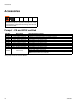
Accessories Accessories Modular box lubricators are not approved for use in hazardous locations or explosive atmospheres unless all accessories, components and wiring meet all local and national codes. Pumps* - CE and ATEX certified Part No. Description 24J391 24J392 24J393 24J394 24J395 24J396 24J397 24J398 24J399 3/16 in. Suction Fed Pump 1/4 in. Suction Fed Pump 3/8 in. Suction Fed Pump 3/16 in. Gravity Fed Pump 1/4 in. Gravity Fed Pump 3/8 in. Gravity Fed Pump 3/16 in. Pressure Fed Pump 1/4 in.
Accessories Motors Part No.
Accessories Electric Heaters Part No. Voltage Watts Thermostat Voltage Temperature Range Watt Density Hazardous Reservoir Area Size: pints Rating (liters) 564058 115 150 115/230 -100°F to 500°F (38°C to 260°C) 20w/in2 Class 1 Group D 557207 12 200 120 60°F to 240°F (16°C to 116°C) 22w/in2 Class 1 Group B 4 (1.89) 6 (2.84) 8 (3.79) 12 (5.68) 16 (7.57) 24 (11.36) 32 (15.14) 40 (18.93) 4 (1.89) 6 (2.84) 8 (3.79) 12 (5.68) 16 (7.57) 24 (11.36) 32 (15.14) 40 (18.
Technical Data Technical Data Modular Box Lubricator 3/16” US Maximum Outlet Pressure 7500 psi 1/4” 6000 psi 3/8” 2500 psi Pump Size Temperature Operating Temperature Range Fluid Viscosity Dispensing Fluid Viscosity Materials of Constructions Wetted Materials Drive Speed Drive Speed -20°F to 140°F Metric Maximum Outlet Pressure 51.71 MPa 517.1 bar 41.37 MPa 413.7 bar 17.24 MPa 172.
Reservoir and Mounting Dimensions Reservoir and Mounting Dimensions Dimensions are shown in inches (mm). DIM A 5.5 (139.7) 6.1 (154.94) .13 (3.31) 4X SLOTS .438 X .688 (11.13 X 17.48) DIM B .875 (22.23) 3.75 (95.25) Dimensions: All Reservoirs Option A Code A or J B or K C or L D or M E or N F or P G or R H or S 14 Reservoir Size Pints (Liters) 4 (1.89) 6 (2.84) 8 (3.79) 12 (5.68) 16 (7.57) 24 (11.36) 32 (15.14) 40 (18.93) Dimension A Inch (mm) 5.63 (143.0) 7.38 (187.4) 10.88 (276.4) 16.13 (409.
Drive Options and Dimensions Drive Options and Dimensions Dimensions are shown in inches (mm). Refer to the Part Number Key, page 2 to determine your specific drive. Direct End Rotary Option D, Code A or E (page 2) - Option D, Code A shown. 2.25 (57.15) 2.375 (60.33) FROM C/L OF SLOT .50 (12.7) #5 WOODRUFF KEY 2.81 (71.37) End Ratchet Option D, Code B or F (page 2) - Option D, Code B shown 2.25 (57.15) 2.375 (60.33) FROM C/L OF SLOT .50 (12.7) #5 WOODRUFF KEY 2.81 (71.
Drive Options and Dimensions End Rotary Ratchet Option D, Code C, D, G, or H (page 2) - Option D, Code C or D shown Code Ratio C or G D or H 37.5:1 75:1 Max Input Speed 800 rpm 800 rpm 1.94 (49.28) 2.375 (60.33) FROM C/L OF SLOT .38 (9.65) #3 WOODRUFF KEY 4.61 (117.09) Double Reduction End Rotary Option D, Code J - N (page 2) - Option D, Code J-N shown Code J K L M N Ratio 25:1 50:1 100:1 200:1 300:1 2.25 (57.15) 4.375 (111.13) FROM C/L OF SLOT .50 (12.7) #3 WOODRUFF KEY 4.86 (123.
Drive Options and Dimensions Angle Rotary Drive Option D, Code P - T and Z (page 2) Code P R S or Z T Ratio 25:1 50:1 188:1 375:1 Right Hand Rear Drive Option D, Code P-T Shown 6.735 (171.07) FROM C/L OF SLOT 2.85 (72.39) .50 (12.7) #3 WOODRUFF KEY 1.35 (34.37) FROM C/L OF SLOT /HIW +DQG 5HDU 'ULYH 2SWLRQ ' &RGH = 6KRZQ 8.359 (212.32) FROM C/L OF SLOT .50 (12.7) #3 WOODRUFF KEY 3A2100C 2.85 (72.39) 1.35 (34.
Drive Options and Dimensions Gear Reducer Option D, Code U - Y (page 2) - Option D, Code U-Y shown Code U V W X Y Ratio 100:1 150:1 200:1 300:1 400:1 4.95 (125.73) 11.75 (298.45) 5.75 (146.
Motor Mounting Bases and Dimensions Motor Mounting Bases and Dimensions Dimensions are shown in inches (mm). Refer to the Part Number Key, page 2 to determine your specific mounting base. Motor Mounting Bases Option A, Code J - N (page 2) - These selections may only be used with double reduction end rotary type drives, Option D, Code J - N. D 9.4 (238.76) 7.3 (185.42) .63 (16.00) 3.0 (76.2) 6.75 (171.45) 8.0 (203.2) EX .406 ( 10.32) B 2.0 (50.8) C A 6.9 (175.26) .75 (19.
Motor Mounting Bases and Dimensions Motor Mounting Bases Option A, Code P - S (page 2) - These selections may only be used with gear reducer type drives, Option D, Code U-Y. 14.0 (355.6) 12.0 (304.8) 10.0 (251.46) 4X .563 B 15.0 (381.0) A 11.75 (298.45) 2.74 (69.60) .63 (16.00) Dimensions Option A Code P R S 20 Description Pint (liters) Base, Drip Pan 24 (11.36) Base, Drip Pan 32 (15.14) Base, Drip Pan 40 (18.93) Dimension A Inch (mm) 46.00 (1168.4) 53.00 (1346.2) 60.00 (1524.
Level Controller Dimensions Level Controller Dimensions Dimensions are shown in inches (mm). Refer to part number key, page 2 to determine your specific level controller. RENS Level Controller Option B, Code 4 - 6 (page 2) - Automatic fill option. Does not require a pump station for mounting. Mounted only on the front of the reservoir. Requires a maximum inlet pressure of 5 psi (0.03 MPa, 0.34 bar). 5.56 (141.22) A 7.31 (185.93) 2.19 (55.
Level Controller Dimensions GARZO Level Controller Option B, Code 7 - 9 (page 2) - Automatic fill option. Mounts on the front of the reservoir. Requires a 0 - 70 psi (00.48 MPa, 0 - 4.82 bar) inlet supply. Switch actuates when a 1/2 to 3/4 loss of oil level occurs in the controller. ELECTRICAL DATA Contacts: Single Pole, Double-Throw Contact Rating: 15 amps at 115/230 or 480 VAC 0.5 amps at 125 VDC 0.25 amps at 250 VDC Switch Rating: Class 1, Group D A 13.9 (353.06) 2.78 (70-63) 4.13 (104.9) 5.88 (149.
Notes Notes 3A2100C 23
Graco Standard Warranty Graco warrants all equipment referenced in this document which is manufactured by Graco and bearing its name to be free from defects in material and workmanship on the date of sale to the original purchaser for use. With the exception of any special, extended, or limited warranty published by Graco, Graco will, for a period of twelve months from the date of sale, repair or replace any part of the equipment determined by Graco to be defective.