Setup - Operation HFRL and HFRS 3A2175A EN Hydraulic, Plural-Component, Fixed-Ratio Proportioner. For pouring and dispensing laminates and silicones. For professional use only. Not approved for use in explosive atmospheres or hazardous locations. Important Safety Instructions Read all warnings and instructions in this manual. Save these instructions. See page 4 for model information and maximum working pressure. Patent Pending ti18208a Silicone unit shown.
Contents Related Manuals . . . . . . . . . . . . . . . . . . . . . . . . . . . 3 Models . . . . . . . . . . . . . . . . . . . . . . . . . . . . . . . . . . . 4 HFR-Laminate (HFRL) . . . . . . . . . . . . . . . . . . . . 4 HFR-Silicone (HFRS) . . . . . . . . . . . . . . . . . . . . . 6 Warnings . . . . . . . . . . . . . . . . . . . . . . . . . . . . . . . . 10 Important Two-Component Material Information 14 Isocyanate Conditions . . . . . . . . . . . . . . . . . . . . 14 Material Self-ignition . . . . . . .
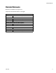
Related Manuals Related Manuals Manuals are available at www.graco.com.
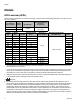
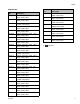
Models Models HFR-Laminate (HFRL) HFRL models are designed for use with low viscosity, unheated urethane laminating adhesives at flow rates of up to 30 cc/sec (4 lb/min).
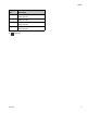
Models HFRL Models Part Number HFRL01 HFRL02 HFRL03 HFRL04 HFRL05 HFRL06 HFRL07 Description Description HFRL23 ★ HFR for Lamination, 230/1, 1.00:1, 80/80, Carbon Steel HFR for Lamination, 400/3, 1.60:1, 80/50, Carbon Steel HFRL24 ★ HFR for Lamination, 230/1, 1.08:1, 86/80, Carbon Steel HFR for Lamination, 400/3, 1.63:1, 65/40, Carbon Steel HFRL25 ★ HFR for Lamination, 230/1, 1.16:1, 100/86, Carbon Steel HFR for Lamination, 400/3, 1.
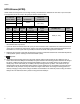
Models HFR-Silicone (HFRS) HFRS models are designed for use with high viscosity, unheated silicone adhesives at flow rates of up to 20 cc/sec. The equipment can be ran at up to 20 cycles per minute continuous duty. Full Load Peak Amps Per Phase* Voltage (phase) 55 A 230V (1) 55 A ★ 400V (3) A Pump Size 15 5 5 5 10 5 * B Pump Size 80 50 30 20 10 10 System Watts cc/stroke 95 55 35 25 20 15 Maximum Fluid Working Pressure ‡ psi (MPa, bar) 12,650 Required cpm@ Flow** 11.3-12.
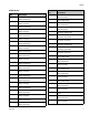
Models HFRS Models Part Number Part Number Description Description HFRS23 HFR for Silicone, 230/1, 1:1, Carbon Steel, 55/55 Feed HFR for Silicone, 230/1, 5.33:1, Carbon Steel, 5/5 Feed HFRS24 ★ HFR for Silicone, 230/1, 1:1, Carbon Steel, 5/5 Feed HFR for Silicone, 400/3, 5.33:1, Carbon Steel, 55/55 Feed HFRS25 ★ HFRS03 ★ HFR for Silicone, 400/3, 1:1, Carbon Steel, 55/55 Feed HFR for Silicone, 400/3, 5.
Models Part Number 8 Description Part Number Description HFRS45 HFR for Silicone, 230/1, 10:1, Carbon Steel, 55/55 Feed HFRS67 HFR for Silicone, 230/1, 5.33:1, Stainless Steel, No Feed HFRS46 HFR for Silicone, 230/1, 10:1, Carbon Steel, 55/5 Feed HFRS68 ★ HFR for Silicone, 400/3, 5.
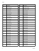
Models Part Number Description HFRS89 HFR for Silicone, 230/1, 10:1, Carbon Steel, No Feed HFRS90 ★ HFR for Silicone, 400/3, 10:1, Carbon Steel, No Feed HFRS91 HFR for Silicone, 230/1, 10:1, Stainless Steel, No Feed HFRS92 ★ HFR for Silicone, 400/3, 10:1, Stainless Steel, No Feed ★ 3A2175A approved.
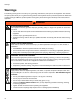
Warnings Warnings The following warnings are for the setup, use, grounding, maintenance, and repair of this equipment. The exclamation point symbol alerts you to a general warning and the hazard symbol refers to procedure-specific risk. Refer back to these warnings. Additional, product-specific warnings may be found throughout the body of this manual where applicable. WARNING ELECTRIC SHOCK HAZARD This equipment must be grounded. Improper grounding, setup, or usage of the system can cause electric shock.
Warnings WARNING FIRE AND EXPLOSION HAZARD Flammable fumes, such as solvent and paint fumes, in work area can ignite or explode. To help prevent fire and explosion: • • • • Use equipment only in well ventilated area. Eliminate all ignition sources; such as pilot lights, cigarettes, portable electric lamps, and plastic drop cloths (potential static arc). Keep work area free of debris, including solvent, rags and gasoline.
Warnings WARNING EQUIPMENT MISUSE HAZARD Misuse can cause death or serious injury. • Do not operate the unit when fatigued or under the influence of drugs or alcohol. • Do not exceed the maximum working pressure or temperature rating of the lowest rated system component. See Technical Data in all equipment manuals. • Use fluids and solvents that are compatible with equipment wetted parts. See Technical Data in all equipment manuals. Read fluid and solvent manufacturer’s warnings.
Warnings 3A2175A 13
Important Two-Component Material Information Important Two-Component Material Information Isocyanate Conditions Spraying or dispensing materials containing isocyanates creates potentially harmful mists, vapors, and atomized particulates. Read material manufacturer’s warnings and material MSDS to know specific hazards and precautions related to isocyanates. Prevent inhalation of isocyanate mists, vapors, and atomized particulates by providing sufficient ventilation in the work area.
A (Red) and B (Blue) Components Changing Materials • When changing materials, flush the equipment multiple times to ensure it is thoroughly clean. • Always clean the fluid inlet strainers after flushing. • Check with your material manufacturer for chemical compatibility. • Most materials use ISO on the A (Red) side, but some use ISO on the B (Blue) side. See the following section. A (Red) and B (Blue) Components IMPORTANT! Material suppliers can vary in how they refer to plural component materials.
Typical HFRS System Typical HFRS System M L A N E C D P N ti18208a P G F J, K B J, K H FIG.
Typical HFRL System Typical HFRL System AA AE AD AL AC AG AF AB AJ, AK AH AL ti18209a FIG.
Component Identification Component Identification BP BF BX BA BH BG BR BY BJ CE BS BV (Located on opposite side of machine) BH BG ti18210a FIG. 3: Component Identification, shown with shrouds removed Key for FIG. 4.
Component Identification HFRS Material Inlet (3000 psi Max) HFRL Material Inlet (250 psi Max) BJ BJ BH BG CD ti18211a BG ti18212a BJ Fluid Manifold (FM) Detail BD BZ BK BL CA Rear View BE CB CC BU BT BB BM BN BC ti9880a1 24C352_313998_4e FIG.
Component Identification Main Power Switch Circuit Breakers Located on rear of machine. The circuit breakers are located on the panel assembly mounted directly behind the disconnect switch panel on the right side of the enclosure. For more information about items on the power distribution panel, see manual 3A2176 ti18213a The main power switch turns power ON and ti18214a OFF . The main power switch does not turn CB5 pumps on. CB1 ti18215a 20 Ref.
Component Identification Hydraulic Power Pack DG DB DF DE DH DA DD FIG.
Component Identification Motor Control Module (MCM) For MCM location, see reference MA in FIG. 4 on page 19. When installed, the end of the MCM with the power input connection (12) faces down and the end with the access cover (A) faces up. NOTICE If the Motor Control Module is replaced, the selector switch must be set prior to initial startup of the Motor Control Module or damage may occur. See HFR Repair manual for details, see Related Manuals on page 3.
Component Identification Ref Description A Access Cover B LEDs C Warning Label 1A, 1B CAN Connections 2 Three-way Splitter to: Oil Low Level Sensor, Dispense Valve Solenoid, and Footswitch 3 Oil Temperature Sensor 5 Electric Motor Temperature Sensor 6 LVDT 7 Three-way Splitter to: Hydraulic Directional Valve, Oil Overtemperature Switch 8 Pressure Transducer B (Blue) side 9 Pressure Transducer A (Red) side 10 Not used 11 Motor Position Sensor 12 MCM Power Input Connection 13 M
Component Identification Advanced Display Module (ADM) User Interface EB EC EA ED EE EF EH EG TI12362a1 FIG. 7: ADM Component Identification - Front Buttons Callout Button Function Callout Button EA Enables/disables system. When system is disabled, temperature control and dispense operation are disabled. ED Soft Keys Defined by application using ADM. EE Cancel Cancel a selection or number entry while in the process of entering a number or making a selection. System Displays system status.
Component Identification EJ ES EK EL EM EN ER EP ti12363a1 FIG.
Component Identification Main Display Components The following figure calls out the navigational, status, and general informational components of each screen. For details regarding the user interface display see Advanced Display Module (ADM) Operation, page 55. Current date and time Mode Previous screen Current screen Next screen Faults, Status Enter/Exit screen Previous screen no. Current screen no. Function display Next screen no. FIG.
Component Identification Fluid Control Module (FCM) FA FC E ti12337a1 FB FF ti12336a1 FD FIG.
Dispense Valve Overview Dispense Valve Overview The HFRL and HFRS systems will be provided exclusively with MD2 dispense valves. The MD2 dispense valve is an example of a solenoid controlled dispense valve. When the trigger is pulled the signal requests the dispense to start. When the machine sees the signal, fluid rises to dispensing pressure and the valve is opened to begin dispensing. When the trigger is released, the solenoid signals that the dispense is finished.
Setup Setup Perform this setup procedure to secure all necessary machine connections for machine operation. 1. Locate HFR. a. Locate HFR on a level surface. See Dimensions on page 94 for space requirements. b. 300 mA if installed. Electrical Cord Wires by Model 230V, 1 phase: L1, L2, GND 400V, 3 phase: L1, L2, L3, N, GND Use 5/32 or 4 mm hex allen wrench to connect the two or three power leads to L1, L2, and L3, as applicable. Connect green to ground (GND). Do not expose HFR to rain.
Setup Power conversion equipment can be sensitive to voltage fluctuations on incoming power. The Motor Control Module falls under the category of power conversion equipment because energy is stored on a capacitive bus and then modulated to control a brushless motor.
Setup 4. Connect regulator assemblies (If Equipped) b. Ensure A (Red) and B (Blue) inlet valves (FV) are closed. NOTE: Systems equipped with a fluid regulator on the material inlet will not be fully assembled due to shipping. The regulator assembly will be detached and boxed separately. a. Attach the male nipple located on the regulator assembly to the female swivel located on the end of the pump assembly. b.
Setup 6. Connect pressure relief lines (R) 7. Connect hose a. Turn main power OFF Do not install shutoffs downstream of the PRESSURE RELIEF/DISPENSE valve outlets (BA, BB). The valves function as overpressure relief valves when set to DISPENSE . Lines must be open so valves can automatically relieve pressure when machine is operating. If circulating fluid back to the supply drums, use high pressure hose rated to withstand the maximum working pressure of this equipment. a.
Setup 9. Connect whip hose to MD2 valve component A (Red) and component B (Blue) fluid inlets. a. Lift the reservoir (LR) out of the bracket (RB) and remove the container from the cap. 10. Pressure check hose Pressure check hoses for leaks. If no leaks, secure the hoses and airlines together to protect from damage. 11. Ground system RB LR This equipment must be grounded. 24C352_313998_8e a. HFR: grounded through power cord. See step 3 on page 29. b. Fluid supply containers: follow your local code.
Setup i. 15. Install dispense valve a. Navigate to System Screen 2 and select the MD2 dispense valve from the “Dispense Valve” drop down menu. See System Screen 2 on page 62. b. Set pressure relief valves (SA, SB) to RELIEF. c. If dispense valve has a trigger safety lock, engage the trigger safety lock. If equipped, check fluid pressure gauges (GA, GB) to ensure proper pressure balance.
Operation Operation Startup h. Open fluid inlet valves (FV), if equipped. Check for leaks. Do not operate HFR without all covers and shrouds in place. FV 1. Use feed pumps to load fluid ti10002a1 NOTE: The HFR is tested with oil at the factory. Flush out the oil with a compatible solvent before dispensing. See Flushing on page 39. a. Check that all machine connections are setup. See Setup procedure, page 29. b. Verify both feed supply systems and the HFR are connected to an air supply. c.
Operation 2. Calibrate HFR The HFR calibration procedure is a two step process. The first step, Learn Mode, must be performed whenever the pump line is rebuilt or if any other maintenance is performed that may affect the mechanical tolerances in the pump line. If the machine does not appear to be utilizing the full extent of the pump stroke, or if the machine appears to be contacting the end of the hydraulic cylinder, follow the Learn Mode procedure.
Operation i. Select the Cal. 1 Shot Average field then press to erase the value. j. a. Navigate to the Shots screen. Select the Cal. Point 1 of 2 text box. k. Press shot. l. Weight the material dispensed and enter the weight in the text box. or the footswitch to dispense a Cal. 1 m. Repeat the previous two steps three more times. The logic will automatically average the readings and provide the result in the second text box in the row. n. Select the Cal.
Operation Shutdown Pressure Relief Procedure 1. Park pumps. 1. Shut off feed pumps and agitator, if used. 2. Turn PRESSURE RELIEF/DISPENSE valves (SA, a. From the Home screen, press Standby mode. b. and select SB) to PRESSURE RELIEF/CIRCULATION . Route fluid to waste containers or supply tanks. Ensure gauges drop to 0. Press . Material will dispense. Pump will park automatically. Once pump is parked, pump will stop moving.
Operation Flushing • To maintain grounding continuity when flushing or relieving pressure, hold a metal part of dispense gun firmly to the side of a grounded metal pail, then trigger gun. Flush equipment only in a well-ventilated area. Do not dispense flammable fluids. Do not turn on heaters while flushing with flammable solvents. • Flush out old fluid with new fluid, or flush out old fluid with a compatible solvent before introducing new fluid. • Use the lowest possible pressure when flushing.
Operation Adjusting Material Inlet Pressure Using the Material Regulator 8. Place the pressure relief valve on the manifold into the recirculation position. 9. Slowly increase the air pressure on the material regulator to allow material to flow though the pump and out the bleed hose. The required material pressure will vary depending on the material viscosity and flow rate. NOTICE Care must be taken when applying pressure to systems equipped with a material pressure regulator on the inlet assembly.
Operation Pressure Balancing Using the Orifice Valve Assemblies 1. Before installing, insert the allen wrench into the hex end of the orifice valve to adjust the needle position. 2. Verify the needle valve is in the fully open position by turning counter-clockwise until rotation stops. After installation, the needle valve can be turned clockwise to further increase pressure. The MD2 valve for HFRL and HFRS systems is provided with orifice valve blocks on both of the inlet ports.
Operation NOTE: In general, the flow area ratio of the orifice valves should be equal to the material ratio, but it will also be influenced by differences between "A" and "B" material viscosities and flow characteristics. For flowable materials, start with a smaller orifice combination to increase pressure. For heavy viscosity, paste materials, start with a larger orifice combination.
Maintenance Maintenance Change Break-in Oil After initial break-in, see Table 5 for recommended frequency of oil changes.
Maintenance Advanced Display Module (ADM) Install Upgrade Token To install software upgrades: 1. Use software token 16H821. See Graco Control Architecture™ Module Programming manual for instructions. Replace Battery A lithium battery maintains the ADM clock when power is not connected. To replace the battery: 1. Disconnect power to the ADM. NOTE: This can be done by removing the CAN cable from the bottom of the ADM.
Maintenance Motor Control Module (MCM) Install Upgrade Token NOTE: The MCM connection to the system is temporarily disabled during the installation of upgrade tokens. Keep heat sink fins clean at all times. Clean them using compressed air. NOTE: Do not use conductive cleaning solvents on the module. 1. Use software token 16H821. See Graco Control Architecture™ Module Programming manual for instructions.
Maintenance Fluid Control Module (FCM) Fluid Inlet Strainer Screen (Not included on HFRS systems) Install Upgrade and Key Tokens NOTE: FCM connection to system is temporarily disabled during the installation of upgrade or key tokens. 1. Use software token 16H821. See Graco Control Architecture™ Module Programming manual for instructions. NOTE: Upgrade all modules in the system to the software version on the token, even if you are replacing only one or two modules.
Maintenance 6. Open the fluid inlet valve, ensure that there are no leaks, and wipe the equipment clean. Proceed with operation. IsoGuard Select™ System (Not included on HFRS systems) 59d 59g* NOTE: The IsoGuard Select system is included on all HFRL 59h systems. It is available separately for HFRS systems as kit 24M154. 59j 59k ti9886a1 FIG. 17. Fluid Inlet Strainer Check the condition of the A (Red) pump IsoGuard Select fluid daily.
Maintenance 7. Thread the reservoir onto the cap assembly and place it in the bracket (RB). 8. Push the supply tube (ST) approximately 1/3 of the way into the reservoir. 9. Push the return tube (RT) into the reservoir until it reaches the bottom. NOTE: The return tube must reach the bottom of the reservoir, to ensure that isocyanate crystals will settle to the bottom and not be siphoned into the supply tube and returned to the pump. 5.
Troubleshooting Troubleshooting Light Tower (Optional) Signal Description Green on only System is powered up and there are no error conditions present Yellow on An advisory exists Red flashing A deviation exists Red on The system is shut down due to an alarm occurring. Before performing any troubleshooting procedure: 1. Perform Pressure Relief Procedure on page 38. 2. Turn main power OFF. 3. Allow equipment to cool.
Troubleshooting Problem Material imbalance.
Troubleshooting ADM Troubleshooting CJ CS CK CL CM CN CR ti12363a1 CP FIG. 19: ADM Component Identification - Rear ADM Module Status LEDs (CN) Conditions Module Status LED Signal Description Green on System is powered up. Yellow on Communication in progress. Red solid ADM hardware failure. Red flashing Uploading software. USB Module Status LEDs (CL) Conditions Module Status LED Signal Description Green flashing System is powered up.
Troubleshooting Motor Control Module For MCM location, see reference MA in FIG. 4 on page 19. Diagnostic Information 7 Table 3: LED Status Signal Module Status LED Signal Description Green on System is powered up. Yellow on Internal communication in progress. Red solid MCM hardware failure. Replace MCM. Red flashing fast Uploading software. Red flashing slow Token error. Remove token and upload software token again. LED Signals r_257396_3b9905_01b FIG.
Troubleshooting Acceptable Size and Duration of Power Line Voltage Fluctuations The Motor Control Module is designed to withstand voltage fluctuations from the incoming power supply. If the incoming power supply goes outside of the tolerable range, an over-voltage condition is flagged and the system shuts down in an alarm state. Excessive or repeated over-voltage may permanently damage hardware. The chart below shows the permissible magnitude and duration of temporary over-voltage events.
Troubleshooting Fluid Control Module Diagnostic Information Module Status LED Signal Diagnosis Green on System is powered up Yellow Internal communication in progress Red solid FCM hardware failure. Replace FCM. Red flashing fast Uploading software Red flashing slow Token error. Remove token and upload software token again. Module Status LEDs ti12337a1 FIG.
Advanced Display Module (ADM) Operation Advanced Display Module (ADM) Operation When main power is turned on by turning the main power switch (MP) to the ON position, the splash screen will be displayed until communication and initialization is complete. 7. If L-Head is installed, define L-Head control details. See Mix Head Operating Details Screen, page 62. 8. Define level sensors and refill settings. See Supply Screen, page 64. 9. If Night mode will be used, define Night mode settings.
Appendix A - ADM Icons Overview Appendix A - ADM Icons Overview Icon Function Icon Function Access Learn Mode Calibration screen Select mode Access Weight Calibration and Material Specific Gravity Entry screen Move L-Head Cleanout Rod Pump Graphic With a mix head installed: Turns on the mix head hydraulics and puts the machine in low pressure circulation. Calibration Screen, Learn Mode: Move pump Press a second time to turn off instigated system action.
Appendix A - ADM Icons Overview Icon Function Tank Blanket Heater Primary Heater Heated Hose Chiller Current and setpoint temperature for primary heater. Not displayed if heat zone is not enabled. Current and setpoint temperatures for heated hose. Not displayed if heat zone is not enabled. Current and setpoint temperatures for tank blanket. Not displayed if heat zone is not enabled. Current and setpoint temperatures for chiller. Not displayed if heat zone is not enabled.
Appendix B - ADM Setup Screens Overview Appendix B - ADM Setup Screens Overview The ADM will start in the Run screens at the “Home” screen. From the Run screens, press to access the Setup screens. If the Setup screens password is turned on, use the ADM keypad to enter the password then press From the Setup screens, press to access the Run screens. For Run screens information, see Appendix C - ADM Run Screens Overview on page 68. FIG. 22 shows the flow of the Setup screens. .
Appendix B - ADM Setup Screens Overview Shots Screen Sequences Screen This screen allows the user to edit shot definitions. The contents of this screen change based on the Dispense and Control Mode selections. Shots may be defined by pressure or flow rate depending upon the Control Mode selection and by time (duration), volume, or weight depending upon the Dispense Mode selection. See System Screen #1 for Control and Dispense Mode options.
Appendix B - ADM Setup Screens Overview Calibration Screen, Main Calibration Screen, Learn Mode This screen shows calibration information for the system and provides access to other calibration screens. See Calibrate HFR on page 36 for how to use the calibration screens to calibrate the machine. This screen allows the user to calibrate piston position. The piston can be moved to the left and right to obtain the full range of motion.
Appendix B - ADM Setup Screens Overview Calibration Screen, Specific Gravity System Screen 1 This screen allows the user to enter material specific gravities and perform weight calibration shots. See Calibrate HFR on page 36 for how and when to use this screen to calibrate the machine. This screen allows the user to set important system settings. Control Mode can be set to Pressure or Flow.
Appendix B - ADM Setup Screens Overview System Screen 2 Mix Head Operating Details Screen This screen allows the user to set the Gel Timer properties and set which items are installed on the machine. This screen allows the user to define the mix head operating parameters. When enabling the Gel Timer, the user must select one of the 100 available shot definitions to use as the Gel Shot. This shot will be dispensed when the Idle Period expires. The Idle Period will begin after a dispense is completed.
Appendix B - ADM Setup Screens Overview System Screen 3 Keyboard Screen This screen allows the user to edit the labels for the A (Red) and B (Blue) sides of the machine. The labels set for the A (Red) and B (Blue) sides of the machine are displayed throughout the screens. Labels are limited to five characters. This screen is used to edit the A (Red) and B (Blue) labels on the ADM. Use arrow keys to select the desired letter and press to accept the letter. To edit a label: 1. Press . 2.
Appendix B - ADM Setup Screens Overview Maintenance Screen Supply Screen This screen shows shot number and sequence position counters. Press the Enter Screen button and navigate to the drop down box. Press the enter key and scroll to a range of counters to view. Press the enter key again to select the range of counters and display them on the screen. This screen allows the user to specify the operating parameters for off-board, integrated tanks and indicate which positions have level sensors installed.
Appendix B - ADM Setup Screens Overview • Auto Full-Volume • The low level sensor will initiate an automatic refill when it does not see material • Automatic refill will continue until either the high level sensor sees material or until the refill time-out expires • The low level alarm will clear when the condition clears • A button is provided to the user on the run screens to instigate an automatic refill operation at any time, this button can also be used to abort a refill operation Conditioning Scree
Appendix B - ADM Setup Screens Overview Conditioning Screen 2 This screen shows the fluid path for the temperature conditioning components and temperature setpoints for each component. NOTE: If tank blanket heaters or inline heaters are installed along with hose heat, the hose heat setting will be limited to at or below the inline or tank heat setting. Conditioning Screen 3 This screen allows the user to configure Night Mode operation. In Night Mode, the system will cycle on and off periodically.
Appendix B - ADM Setup Screens Overview Advanced Screen 1 This screen allows the user to set the language, date format, current date, time, setup screens password, screen saver delay, and turn on or off silent mode. • • • • • Advanced Screen 2 • This screen allows the user to set the units of measure. • Advanced Screen 3 Disable Modifying Temp Setpoint: Check this box to disable modifying temperature setpoints from the Status run screen.
Appendix C - ADM Run Screens Overview Appendix C - ADM Run Screens Overview Run screens are divided into five major sections: status, errors, events, and maintenance. The following diagram demonstrates the flow of the Run screens beginning with the Home screen. Home Status Errors #1 Events #1 Errors #2 Events #2 Errors #... Events #... Maintenance FIG. 23: Run Screens Navigation Diagram Home Screen The Home screen is the first screen that displays in the Run screens.
Appendix C - ADM Run Screens Overview Home Screen, Standby Mode Home Screen, Shot Mode In Standby Mode, the user can enable heating, park the pumps, refill the tanks, circulate materials. This mode allows the user to select one of 100 predefined shot numbers. See Shots Screen on page 59 for information about editing shot definitions. To use a predefined shot: 1. Enter shot mode. 2. Press and use the numeric keypad to enter the desired shot number. 3. Press the Enter button ber.
Appendix C - ADM Run Screens Overview Home Screen, Sequence Mode Home Screen, Operator Mode This mode allows the user to select one of five sequences (A-E). The progress bar on the bottom of the screen shows the progress of a shot dispensing from the selected sequence. See Sequences Screen on page 59 for information about editing sequence definitions. This mode allows users to set a pressure or flow rate to dispense material without using predefined shot information.
Appendix C - ADM Run Screens Overview Home Screen, Night Mode Home Screen, Disabled Mode In Night Mode, the system will cycle on and off periodically. The recirculation on/off cycle begins automatically upon entering Night Mode. See Conditioning Screen 3 on page 66. When this mode is selected, the machine will not be able to dispense or condition (heat/cool) material. The setup screens cannot be accessed while in Disabled mode. Use the Select mode button to exit Disabled mode.
Appendix C - ADM Run Screens Overview Status Screen Status Screen, Conditioning Control The status screen provides all of the operational functionality of the Home screen except for operating mode selection. Refer to the Home screen and operating mode descriptions for information on this functionality. This screen allows users to turn on and off heat zones individually or all at once. The grey circles indicate that a zone is off and green circles indicate that a zone is on.
Appendix C - ADM Run Screens Overview Errors Screens Maintenance Screen 1 This screen shows users a list of errors that have occurred in the system. Each error entry includes a description and error code along with a date and time stamp. There are 5 pages, each holding 10 errors. The 50 most recent errors are shown. This screen displays historical information for each pump in the system. The Batch counters are resettable and count both material usage and pump cycles.
Appendix D - ADM Error Codes Appendix D - ADM Error Codes Error Code A4H3 DEH3 MBH3 P1H3 P4H3 T4H3 WDF3 WDD3 0500 05A1 A4A6 A4B5 A4A3 A4B1 A4A2 A4B4 A4A7 A4B8 A4H1 A4M1 74 Error Name Error Description Mix Head Motor Overload Soft Stop Asserted Low Mix Head Oil Level Low Accumulator Pressure High Accumulator Pressure High Mix Head Oil Temp.
Appendix D - ADM Error Codes Error Code A4N1 A7A6 A7B5 A7A3 A7B1 A7A2 A7B4 A7A7 A7B8 A8A6 A8B5 A8A3 A8B1 A8A2 A8B4 A8B7 A8B8 A9C1 B9C0 Error Name Error Description Motor Over Current A hardware current fault has occurred causing a system shutdown Red Blanket Control Fault Blue Blanket Control Fault Red Inline Control Fault Blue Inline Control Fault Red Hose Control Fault Blue Hose Control Fault Red Chiller Control Fault Blue Chiller Control Fault No Red Blanket Current No Blue Blanket Current No
Appendix D - ADM Error Codes Error Code CAC1 CAC3 CAC4 CAC5 CAC6 CAC7 CAA6 CAB5 CAA3 CAB1 CAA2 CAB4 CAA7 CAB8 D1A1 D2A1 D3A1 Error Name Comm. Error Motor Comm. Error Red Tank Comm. Error Blue Tank Comm. Error Mix Head Comm. Error Mix Head 2 Comm. Error Ratio Monitor Comm. Error Red Blanket Comm. Error Blue Blanket Comm. Error Red Inline Comm. Error Blue Inline Comm. Error Red Hose Comm. Error Blue Hose Comm. Error Red Chiller Comm.
Appendix D - ADM Error Codes Error Code Error Type Error Name Error Description DFA1 Pump Not Parked The pump failed to reach the park position DSC0 Pumps Not Defined The type or size of the Red or Blue material pumps have not Alarm been defined F7D1 L111 L122 L311 L322 L6A1 L6B2 Cause Orifices blocked Hose blocked Deviation Dispense valve failed to open Properly setup the system Failure of the dispense When the pump tried to stall to valve pressure the pump traveled Pump Failed more than it
Appendix D - ADM Error Codes Error Code Error Name Error Description N4A1 The MCM attempted to move Pump Failed the pump but no movement to Move was detected P400 Thermal Pressure Rise P4A1 P4B2 P4D0 P6A1 P6B2 78 Error Type Cause Solution Visually check to ensure the pump is moving, if not Motor failure ensure the motor is wired properly If motor is moving but pump is not and pressure is not Hydraulic power pack building they hydraulic power pack may need failure servicing Check to ensure the
Appendix D - ADM Error Codes Error Code T1A6 T1B5 T1A3 T1B1 T1A2 T1B4 T1A7 T1B8 T3H1 Error Name Red Tank Low Fluid Temp. Blue Tank Low Fluid Temp. Red Inline Low Fluid Temp. Blue Inline Low Fluid Temp. Red Hose Low Fluid Temp. Blue Hose Low Fluid Temp. Red Chiller Low Fluid Temp. Blue Chiller Low Fluid Temp. Oil Temp.
Appendix D - ADM Error Codes Error Code T4C1 Error Name Error Description Error Type The temperature the MCM has reached a level where product Motor Control Alarm life will be decreased High Temp. drastically and has been shutdown for protection The hydraulic oil is at a temperature where performance is impacted significantly and has resulted in a system shutdown T4H1 Oil Temp. Shutdown T4N1 Motor temperature is too high Motor Temp.
Appendix D - ADM Error Codes Error Code T8A7 T8B8 T9A6 T9B5 T9A3 T9B1 T9C6 T9C5 T9C3 T9C1 T9C2 T9C4 T9C7 T9C8 V1H1 V4A6 V4B5 V4A3 V4B1 V4A2 V4B4 V4A7 V4B8 Error Name No Cooling Red Chiller No Cooling Blue Chiller Error Description Cause Solution Alarm Tripped circuit breaker Visually check circuit breaker for a tripped condition Alarm Disconnect the valve and measure the voltage across the wires when the chiller is running to ensure 24V is Defective cooling valve being delivered to the va
Appendix D - ADM Error Codes Error Code V4H0 Error Name Error Description The voltage to the MCM has Motor Control reached an unsafe level and Overvoltage has been shutdown in an attempt to prevent damage Error Type Alarm W0U0 USB Update The ADM tried to upload a Failed system settings file but failed WBH1 Motor An error has been detected on Alarm Encoder Fault the motor position sensor Alarm Cause Solution Supply lines providing high voltage Check incoming voltage to ensure it is below the max
Appendix D - ADM Error Codes Error Code WMC6 WMC5 WMC3 WMC1 WMC2 WMC4 WMC7 WMC8 WMH1 Error Name Red Tank Con. Fault Blue Tank Con. Fault Red Inline Con. Fault Blue Inline Con. Fault Red Hose Con. Fault Blue Hose Con. Fault Red Chiller Con. Fault Blue Chiller Con.
Appendix E - System Events Appendix E - System Events Event Code and String REL00: System Powered On REM00: System Powered Off REB00: Stop Button Pressed RECH0: Learn Mode Executed RENN0: Automatic Cal. Performed RECA1: Red Material SG Modified RECB2: Blue Material SG Modified RENC1: Cal. Point 1 Weight Entered RENC2: Cal. Point 2 Weight Entered RENC4: Cal. Point 1 Weight Erased RENC5: Cal. Point 2 Weight Erased REND0: Ratio Check Dispense REA00: Disp.
Appendix F - USB Operation Appendix F - USB Operation Overview Download Log Files There are 3 main uses for the USB on a GMS system If the “Enable Downloading of USB Logs” is checked, the user can use a USB stick-drive to download the log files.
Appendix F - USB Operation Log Files, Folder Structure FIG. 24: DOWNLOAD, DATAxxxx Folders Each time a stick-drive is inserted into the ADM USB port, a new folder named DATAxxxx is created. The number at the end of the folder name is incremented each time a stick-drive is inserted and data is downloaded or uploaded. In each DATAxxxx folder there is two log files. They are formatted as .csv (comma separated value) files and can be opened by most text editors or data processing programs such as Excel.
Appendix F - USB Operation Example LOG01 File The LOG01 file is the Errors and Events log file. Example LOG02 File The LOG02 file is the Shot Data Log file.
Appendix F - USB Operation Transfer System Settings Use the following process to transfer system settings from one machine to another. 1. Insert a high-quality USB stick-drive into the USB port on the system with the settings to be transferred. Once the download is complete the SETTINGS.TXT file will be located in the “DOWNLOAD” folder. NOTICE The user should never attempt to modify the SETTINGS.TXT file in any way. Graco is not responsible for damages caused by an improperly modified setup file. 2.
Appendix F - USB Operation Update Custom Language Use the following process to customize the text on the ADM. The language file DISPTEXT.TXT can be modified in Excel but must be saved as a Unicode Text file with the extension .TXT in order for it to properly import. 1. Insert a high-quality USB stick-drive into the USB port on the system with the settings to be transferred. Once the download is complete the DISPTEXT.TXT file will be located in the “DOWNLOAD” folder.
Appendix F - USB Operation Example SETTINGS.TXT File Example DISPTEXT.TXT File NOTICE The user should never attempt to modify the SETTINGS.TXT file in any way. Graco is not responsible for damages caused by an improperly modified setup file.
Accessories Accessories Part No. Description 24M154 IsoGuard® Select Assembly with 32 oz reservoir (Included on HFRL units) 24F516 IsoGuard® Select Fluid, 6 Quarts 255244 Footswitch with Guard and 4 meter cable HFR Discrete Gateway Module (DGM) Kits Single DGM Kit, 24F843 Dual DGM Kit, 24F844 DGM only, 24G830 The HFR Discrete Gateway Module (DGM) allows the user to control an HFR through an external control device such as a PLC.
Technical Data Technical Data Maximum Fluid Working Pressure . . . 3000 psi (21MPa, 207 bar) See Models starting on page 4 for specific information Maximum Fluid Temperature . . . . . . . 120°F (50°C) Fluid Inlet Pressure at Inlet Fitting: HFRL Models . . . . . . . . . . . . . . . . 50 psi (345 kPa, 3.4 bar) to 250 psi (1.8 MPa, 18 bar) HFRS Models . . . . . . . . . . . . . . . . 250 psi (1.8 MPa, 18 bar) to 3000 psi (21 MPa, 207 bar) HFRS (Regulated Pressure). . . . . 250 psi (1.
Technical Data Motor Control Module Technical Data Input Specifications Input Line Voltage . . . . . . . . . . . . . . . . . . . . . . . . . . . Input Line Phasing . . . . . . . . . . . . . . . . . . . . . . . . . . . Input Line Frequency . . . . . . . . . . . . . . . . . . . . . . . . . Input Current per Phase. . . . . . . . . . . . . . . . . . . . . . . Maximum Branch Circuit Protection Rating: . . . . . . . Short Circuit Current Rating. . . . . . . . . . . . . . . . . . . .
Technical Data Dimensions 51.8 in. (1316 mm) 24 in. (610 mm)* 5 in. (127 mm)* 15 in. (381 mm)* 37.2 in. (945 mm) 58.1 in.
Technical Data 3A2175A 95
Graco Standard Warranty Graco warrants all equipment referenced in this document which is manufactured by Graco and bearing its name to be free from defects in material and workmanship on the date of sale to the original purchaser for use. With the exception of any special, extended, or limited warranty published by Graco, Graco will, for a period of twelve months from the date of sale, repair or replace any part of the equipment determined by Graco to be defective.