Instructions - Parts InvisiPac™ HM25 Tank-Free™ Hot Melt Delivery System 3A2347T EN For delivering and dispensing hot melt adhesive pellets. For professional use only. Not approved for use in explosive atmospheres or hazardous locations. 1200 psi (8.3 MPa, 83 bar) Maximum Working Pressure 400°F (204°C) Maximum Fluid Operating Temperature 100 psi (0.7 MPa,7 bar) Maximum Air Inlet Pressure Important Safety Instructions Read all warnings and instructions in this manual and in the gun and hose manuals.
Contents Related Manuals . . . . . . . . . . . . . . . . . . . . . . . . . . . 3 Required Tools . . . . . . . . . . . . . . . . . . . . . . . . . . . . 3 Models . . . . . . . . . . . . . . . . . . . . . . . . . . . . . . . . . . 4 Warnings . . . . . . . . . . . . . . . . . . . . . . . . . . . . . . . . . 5 Component Identification . . . . . . . . . . . . . . . . . . . . 8 Setup . . . . . . . . . . . . . . . . . . . . . . . . . . . . . . . . . . . . 14 Grounding . . . . . . . . . . . . . . . . . . . . . . .
Related Manuals Related Manuals Manuals are available at www.graco.com. Component manuals in English: Part Description 3A2805 InvisiPac GS35 Hot Melt Gun Instructions Parts InvisiPac Heated Hose Instructions - Parts 332072 Required Tools • • • • • • • • • Standard allen wrench set Metric allen wrench set Various sizes of crescent wrenches 11/16 in. wrench 3/8 in. ratchet 3/8 in. socket 5/16 in. driver 7/16 in. socket 7/8 in. deep well socket 3A2347T • • • • • • • • • 1 in.
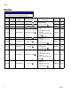
Models Models NOTICE To prevent system damage, verify terminal jumpers are installed correctly before applying power.
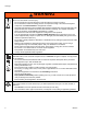
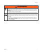
Warnings Warnings The following warnings are for the setup, use, grounding, maintenance, and repair of this equipment. The exclamation point symbol alerts you to a general warning and the hazard symbols refer to procedure-specific risks. When these symbols appear in the body of this manual or on warning labels, refer back to these Warnings. Product-specific hazard symbols and warnings not covered in this section may appear throughout the body of this manual where applicable.
Warnings WARNING EQUIPMENT MISUSE HAZARD Misuse can cause death or serious injury. • Do not operate the unit when fatigued or under the influence of drugs or alcohol. • Do not exceed the maximum working pressure or temperature rating of the lowest rated system component. See Technical Data in all equipment manuals. • Use fluids and solvents that are compatible with equipment wetted parts. See Technical Data in all equipment manuals. Read fluid and solvent manufacturer’s warnings.
Warnings WARNING PERSONAL PROTECTIVE EQUIPMENT Wear appropriate protective equipment when in the work area to help prevent serious injury, including eye injury, hearing loss, inhalation of toxic fumes, and burns. This protective equipment includes but is not limited to: • Protective eyewear, and hearing protection.
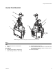
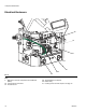
Component Identification Component Identification G3 G2 G4 A G H G1 F E L C D B K Key: A B C D E F G G1 G2 G3 G4 H J K L M N P R S Advanced Display Module (ADM) Electrical Enclosure Pump Air Pressure Regulator Pump Air Pressure Gauge Vacuum Transfer Air Pressure Regulator Vacuum Transfer Air Pressure Gauge Shaker Tube Shaker Head Vacuum Transfer Tube Vacuum Transfer Inlet Funnel Vacuum Transfer 3/8 in.
Component Identification Heated Fluid Manifold AB Z Y U R X AA T W1 W2 ti20442b NOTE: System shown with plastic and metal shrouds removed. FIG.
Component Identification Electrical Enclosure AC AJ P ti20907b AH AG AF FIG. 3 Key: P Multi-Zone Low Power Temperature Control Module (MZLP) AC Incoming Power Connection AF Chassis Ground 10 AG Terminal Blocks and Jumpers AH Heater Relay AJ Incoming Power Terminal Jumpers. See page 19.
Component Identification Advanced Display Module (ADM) User Interface B NOTICE To prevent damage to soft key buttons, do not press the buttons with sharp objects such as pens, plastic cards, or fingernails. NOTE: See Appendix A - ADM on page 104 for complete ADM operation details.
Component Identification Screen Components Screens Order Current date and time Operating Mode Faults, Status Melter Heating Status Melter Actual Temperature Hose and Gun Heating Status Hose Actual Temperature Gun Actual Temperature FIG. 6: Main Screen Components Operating Mode Description Component Status • System Off The system doesn’t have power. Inactive The heating system and pumps are disabled. Warm Up The system is increasing the material to the set temperature.
Component Identification 3A2347T 13
Setup Setup Grounding Attach Components The equipment must be grounded to reduce the risk of electric shock. Improper grounding can cause electric shock. Grounding provides an escape wire for the electric current. The InvisiPac system is equipped with a ground terminal. Have a qualified electrician ground the system using this terminal. See Connect Electrical Cord on page 19. To reduce the risk of electric shock, do not connect electrical cord until after this Attach Components procedure is complete. 1.
Setup d. Install supplied hose clamp around the air motor bracket and funnel base then tighten. 6. Apply pipe sealant to threads then attach steel shaker tube (G) to shaker head (G1). See FIG. 8. NOTICE G2 G3 To prevent shaker head (G1) galling to the shaker tube (G), do not overtighten shaker head onto shaker tube. These should be hand-tightened. G2 G6 G4 G5 ti21130b FIG. 7 G 3. Insert 1.3 in.
Setup 12. Place shaker assembly in an empty adhesive pellets container then fill the container with adhesive pellets. NOTE: To promote optimal system performance, purchase 30 Gallon Vibrating Hopper, 24R136. See installation instructions on page 92. d. Remove plug (247) from the lowest numbered outlet on the melter. Do not use the drain plug (W1). See FIG. 9. NOTE: In the following step, the o-ring side of the hydraulic fitting (68) faces the system. See FIG. 9.
Setup c. For non-Graco guns, attach gun electrical connector to adapter harness (16T916, 16T917, or 16Y828) then attach adapter harness connector to heated hose connector. See Non-Graco Gun Adapter Cables on page 90 to determine which adapter cable to use with your valve. 17. If using the same air for the gun(s), make sure to install the tee in the air line before the ball valve. There should not be anything between the ball valve and the system.
Setup Recommended Air Setup Main Air Line Air In: Less than 50 ft (15.2 m): 3/8 in. More than 50 ft (15.2 m): 1/2 in. 80-100 psi (5.5-6.8 bar, 0.55-6.8 MPa) 30 scfm capacity. No dips in vacuum transfer hose Air In: 3/8 in., 100 psi (6.8 bar, 0.68 MPa), 30 scfm capacity Ensure funnel air is connected Air Filter/Ball Valve at System Air Inlet (Graco Kit 24R707, included) Vacuum: 40 - 80 psi (2.8-5.5 bar, 0.28-0.55 MPa); and at least 65% of hopper shaker air pressure, if used Pump: 20-100 psi (1.4-6.
Setup Connect Electrical Cord NOTE: See Grounding section on page 14. Improper wiring may cause electric shock or other serious injury if work is not performed properly. Have a qualified electrician perform any electrical work. Be sure your installation complies with all National, State and Local safety and fire codes. To reduce the risk of electric shock, perform the entire Attach Components procedure beginning on page 14 prior to connecting electrical cord.
Setup 6. Attach insulated ferrules to the end of each wire. 7. Connect ground wire to chassis ground (AF). See FIG. 14. 106 8. Connect L1, L2, L3, and N as shown in FIG. 15. Not all models use all 4 wires. 9. Use zip ties to secure the electrical cord to the tie-downs located on the top of the inside of the electrical enclosure. Y X 10. Tighten screw-terminals to at least 10 in-lb (1.1 N•m). 11. Install electrical enclosure door. FIG. 14 AF ti20907b 12.
Setup 480V Electrical Circuits 3. On the System 2 screen: For 480V electrical supply, a 480V to 240V step-down transformer must be installed by a qualified electrician. Transformer Sizing For single-phase power, 480V to 240V transformer 24U169 (purchase separately) may be used. See Single-Phase 480V to 240V Transformer, 24U169 on page 100. Minimum transformer rating can be calculated by taking output voltage times the ADM breaker setting.
Setup NOTE: If using a 480V to 240V transformer, the breaker size entered will be two times the 480V rating. If using transformer 24U169, the breaker size should be set to 30 amps and power type should be set to single phase. NOTE: The Schedule function enables the system to automatically enable and disable heating at specified times so that the system is already up to temperature when a shift begins. NOTE: The InvisiPac system limits the amount of power it pulls based on the input circuit breaker size.
Setup 11. On the Targets screen, adjust heated hose and gun temperature settings: NOTE: InvisiPac is a high powered tank-free system that delivers heat faster than traditional tank systems. Tanks are often run at a lower temperature than the application temperature to avoid excessive adhesive degradation since a large volume of adhesive sits at temperature. a. Press to select the channel. c. Use and , shown next to , to adjust heated hose temperature setting to the desired setting for that channel.
Setup PLC Connection A PLC can control and monitor all items shown in the dropdown menus on the System 1 screen in the Setup screens. NOTE: The InvisiPac system ships with two screw-terminal connectors that plug into MZLP connectors H1 and H2. Connectors are located in a bag on the inside of the electrical enclosure front access door. To replace the connectors, order kit 24P176. 1.
Setup PLC Connection Block Diagrams The following block diagrams show how to connect customer inputs and outputs to the InvisiPac MZLP. For convenience, each InvisiPac ships with connector kit 24P176. If a connector is lost or damaged, order kit 24P176 for replacements. MZLP Customer In Customer Output Vin (no polarity) 30 VDC Max FIG. 17: Customer Input MZLP Customer Out Customer In 250 VAC, 2A Max To Customer Input FIG.
Operation Operation NOTE: Only 1/4 in. (6 mm) round hot melt adhesive pellets can be used in the InvisiPac system. PSA-type adhesive pellets will not work in the InvisiPac system. Heating and dispensing hot melt adhesive may create potentially harmful vapors. Read material manufacturer’s warnings and material MSDS to know specific hazards and precautions. Ventilation of the work area may be required. NOTE: See Appendix A - ADM on page 104 for detailed ADM information.
Operation FIG. 1 on page 8. NOTE: Vacuum transfer will not begin operating until pump reaches operating temperature. 12. With the guns open and the system up to temperature, slowly increase pump air pressure until the pump begins to run very slowly. Approximately 20 psi (140 kPa, 1.4 bar) should be sufficient. NOTE: Operation may be erratic below 20 psi (140 kPa, 1.4 bar). To prevent fire and explosion, never exceed the cleaning fluid’s rated temperature.
Operation Automatic Refill 3. Fill the funnel with adhesive pellets. The system uses automatic refill by default. If the automatic refill system is malfunctioning and cannot immediately be fixed, Manual Refill can be used. To use automatic refill: 1. On the System 3 screen (in the Setup screens), select “Automatic” from the Refill mode dropdown. 2. Verify shaker and tube are connected to the system. See Attach Components on page 14. 3.
Operation b. Check pressure gauges (D, F) to verify vacuum transfer and pump air pressures are set as desired. See FIG. 1 on page 8. c. If using Automatic Refill, see Automatic Refill on page 28. d. If using Manual Refill, see Manual Refill on page 27. e. Verify guns are closed. 4. Press Shutdown Press to disable the heaters and pump. The screen will say “Inactive”. If using the Schedule function, the heaters and pump will be disabled automatically at the set time.
Operation Drain the System Enable Schedule Function The Schedule function is automatically enabled when values are entered in the Schedule screen. To disable the Schedule function, delete all values on the Schedule screen or turn the main power switch OFF to prevent system from automatically enabling and disabling the heaters.
Operation 12. Wait until system stops draining or at most 10 minutes. 5. On the System 3 screen (in the Setup screens), verify the Refill Setting is set to “Manual”. NOTE: There will be some residual adhesive in the system. 13. When done performing the procedure that required draining the system, set Refill Setting back to “Auto” on the System 3 screen. Flush To prevent fire and explosion, use the adhesive manufacturer’s recommended cleaning fluid. • Never exceed the cleaning fluid’s rated temperature.
Operation 11. Route the disconnected hose to a waste container. 12. If heating system is disabled, press to enable 20. Remove and replace filter(s) in all gun manifolds. See gun manual. 21. Replace Outlet Filter. See page 34. the heaters and pump. 22. Turn main power switch OFF. 13. Wait for the melter temperature to reach the hot melt cleaning fluid manufacturer’s recommended temperature. NOTE: The pump will not run because the system air inlet ball valve is closed. 14.
Operation Operation Tips to Minimize Charring Set the Pump Idle Time to System Inactive function on the System 3 screen to lowest value that will not interfere with normal operation. This feature automatically disables the heating system if the pump is idle for longer than the preset amount of time. Disabling the heating system minimizes adhesive degradation and limits char formation.
Maintenance Maintenance 6. Insert allen wrench through the outlet filter cap to lift outlet filter (236) out of the system. 7. Discard outlet filter assembly. Replace Outlet Filter The outlet filter is designed to prevent small contaminants from entering the hoses and guns. Inspect filter regularly. Replace the filter after flushing and when you change the adhesive used in the system. 8. Place o-rings (232, 237) provided with new outlet filter onto new outlet filter (236). 9.
Maintenance 4. When the melter temperature is the desired temperature, turn main power switch OFF. 5. Disconnect cable from ADM, push cable through plastic shroud, then remove plastic shroud from system. 6. Place a piece of cardboard beneath the inlet filter cap (215) to route fluid away from system into a waste container in the event the adhesive is a fluid. 7. Use 1 in. socket to remove inlet filter cap (215). f. Go to step 4. 9. Slide new screen (213) into melter base manifold (201). 10.
Maintenance Filter Maintenance Guidelines* Environment Classification Clean Moderate Dusty Replace filter every six months Replace filter every four months Replace filter every two months Pump inlet filter Pump outlet filter Gun manifold filter System air filter Solenoid exhaust filters Feed funnel filter Feed funnel inspection/clean out * These recommendations are service level guidelines - actual service levels required in your factory will vary based on environmental and operating conditions.
Troubleshooting Troubleshooting To avoid injury due to unexpected machine operation initiated by a remote controller, disconnect the customer I/O cable from the system prior to troubleshooting. ADM Error Code Table When an error occurs, press nance screen and press to acknowledge the error. If a Maintenance error occurs, navigate to the Mainteto clear the error. The last digit of the error code indicates the melter, gun, or hose to which the error applies.
Troubleshooting Code A7D0 Description Unexpected Current A7D_ Unexpected Alarm Current, Gun X A7D_ Unexpected Current, Hose X Alarm A8D0 No Current Melter Alarm A8D_ No Current Hose X Alarm A8D_ No Current Gun X Alarm CAC_ Comm Error Module Alarm CACX Missing DB Alarm 38 Type Alarm Cause Unexpected current flow to melter. Solution Replace MZLP. Faulty melter heater(s). Check heater resistance and resistance to ground. Replace faulty heater(s). Unexpected current flow to gun X.
Troubleshooting Code DADX Description Pump Runaway Type Alarm Cause Pump is trying to feed adhesive, no adhesive to feed. DDDX Pump Diving Worn or damaged pump seals Devia- Pump is trying to feed adhesive, no tion adhesive to feed. DE0X Cycle Switch Error Alarm Worn or damaged pump seals No signal from air motor sensor. L6FX Level Sensor Error Alarm No signal from the level sensor.
Troubleshooting Code T4D0 T4D_ T4D_ T6D0 Description High Temp Melter High Temp Hose High Temp Gun Sensor Error Melter Type Alarm Alarm Cause Melter continues to raise above the setpoint. Hose continues to raise above the setpoint. Gun assembly continues to raise above the setpoint. No reading from RTD. Alarm Alarm T6D_ Sensor Error Hose Alarm No reading from RTD. T6D_ Sensor Error Gun Alarm No reading from RTD.
Troubleshooting Code V1I_ Description Low Can Voltage Type Alarm Cause Bad or overloaded power supply. V4I_ High Can Volt- Alarm age No line voltage Alarm Bad or overloaded power supply. V8M_ Incoming line voltage is less than 100 VAC. WJDX Pump Solenoid Error Alarm No voltage draw from air solenoid for air motor. WKFX Fill Solenoid Error Alarm No voltage draw from air solenoid for fill. WSUX USB Invalid Configuration Devia- A valid configuration file can't be tion found for the USB.
Troubleshooting Problem Cause Solution Vacuum transfer not working Air to vacuum assembly missing. Verify the vacuum transfer system air pressure is 40-80 psi (60 psi recommended) Air at system air gauge but not to air to shaker. Check that air line is connected or not pinched. Air is at shaker but there is no feed. Plugged shaker unit, remove from system and remove plug. Adhesive pellets in storage bin not covering shaker head. Shaker unit not vibrating.
Troubleshooting Problem Cause Solution The system will not dispense material. System is not up to temperature. Verify that the system is active. Incorrect temperature set points entered into ADM. Verify the temperature settings are correct. Air motor is not receiving compressed air or air pressure too low. Verify that the pump air pressure is set above 20 psi. Check the Pump Air Solenoid Operation, page 49. Feed pump not feeding adhesive. Repair or replace air control assembly as necessary.
Troubleshooting Problem Cause Solution Unable to achieve 25lb/hr melt rate at the desired adhesive temperature. 1. If the cycle rate is below 33 cpm and the system is still running away The InvisiPac system increase the InvisiPac system temperature by 10°F over the current monitors temperature set point, leave hoses and guns at desired set point. within aluminum mass of melter (202). As melt rates exceed 20 lb/hr a 2.
Troubleshooting Problem Cause Solution Slow start-up time or system takes longer than 10 minutes to startup Wrong setting in ADM breaker setup. Wrong breaker setting on ADM in the breaker setting in the setup screen. Low incoming voltage. Incoming voltage should be 200-240VAC for a 230 volt unit and 380400 VAC for a 400 volt unit. Heater rod defective. Melter and gun manifold. Measure and check heater rods in melter or manifold. Manifold resistance 130-140 ohms. Heated hose defective.
Troubleshooting Problem Cause Solution No adhesive or incorrect amount of adhesive output when all valves are triggered Plugged gun manifold filter. Replace manifold filter. Graco manifold filter in bottom of manifold or inline filter on other manifolds. Clogged hose. Flush or replace hose. Defective solenoid valve. Check that correct voltage is input into valve solenoid. If voltage is correct, replace solenoid. No signal from control to solenoid.
Troubleshooting Problem Cause Solution Adhesive flowing out of one/some valves when not triggered Failed valve in the open position. Replace valve. Adhesive pressure too high. Reduce air pressure to air motor. Gun will not heat. Heat rod failure in manifold. Check resistance on heater rods. Repair manifold if heater rods measure open. Loose cable connection at system or manifold. Check cable connections on both ends of the hose. RTD failure.
Troubleshooting Problem Cause Solution Static shock when touching shaker or adhesive bin. Ground wire not in place on shaker assembly. Some adhesives, flow rates, and ambient conditions can cause excessive static buildup on the shaker tube. Attach a ground wire from the shaft of the shaker unit to a true earth ground. Order shaker grounding kit 24R708. Adhesive not dispensing at the correct time. Guns opening at the wrong time. InvisiPac system does not control the opening and closing of the guns.
Troubleshooting Flush Pressure Relief Valve 3. Plug air line and allow the air motor to cycle. 4. Re-connect air line to relief valve and check whether the system will stall. Perform this procedure when directed in the Troubleshooting table. 1. With the system active at the required adhesive temperature, set the air motor air pressure to 20 psi (140 kPa, 1.4 bar). 5. If system still does not stall, purge ten pump cycles of material through one gun. 6.
Troubleshooting MZLP Troubleshooting Signal Description Green On MZLP is powered up and input voltage is within operating conditions. Yellow On Internal communication in process Red Solid MZLP failure. See troubleshooting table. Red Flashing Software update in process or missing software. Red J3 56 FIG. 25: MZLP LED Signals 234 01 7 89 ti20441b1 Yellow Green MZLP NOTE: The MZLP LED is located on the inside of the electrical enclosure.
Repair Repair NOTE: Some procedures require special tools. Read through each procedure prior to beginning it to ensure you have the required tools to complete the entire procedure. Order any required tools and have them on hand prior to beginning the procedure. NOTICE Disassembly (see FIG. 27): 1. Flush the system. See page 31. 2. Close the bleed-type ball valve installed at the system air inlet to relieve all air pressure in the system. 3. Turn main power switch OFF.
Repair c. Install piston valve (222) onto piston rod (223). Torque to 24-30 ft-lb (33-41 N•m). 2. To protect the seals from the sharp threads, place seal installation tool 15B661 into the throat bore. See FIG. 28. 6. Slide throat bearing (233) over the piston rod (223). Use socket and tap with a rubber mallet to press throat bearing (233) into place and seat the throat u-cup. 235 15B661 203 233 ti20877a FIG. 28 3. Push the piston rod assembly (223) into the melter outlet manifold (203). 4.
Repair Reassembly (see FIG. 31): Replace Pump Inlet Housing Checks 1. Install new o-ring (229), seat (228), and ball (227) then use a 1/2 in. drive ratchet without a socket to install and tighten foot valve (230) onto melter. 2. Install Melter Assembly. See page 56. Replace Pump Cylinder Seals and Piston Seals 254 218 201 239 235 233 234 227 228 229 230 233 224 226 222 257 ti20749a FIG. 31 217 Disassembly (see FIG. 31): 216 1. Flush the system. See page 31. 217 2.
Repair 5. Remove air lines from relief valve (245) and air motor (218) See FIG. 27 on page 51. 14. Remove and discard cylinder seals (217). See FIG. 31. 6. Remove nuts (3) securing melter shield (27) in place then remove melter shield. See FIG. 27 on page 51. Reassembly: 1. Apply grease to seals (217) then install new cylinder seals (217) onto cylinder (216). See FIG. 31. 7. Remove air motor assembly. See FIG. 27 on page 51: a. Remove retaining ring (239). 1303 b. Remove dowel pin (238). c.
Repair Melter 3. Turn main power switch OFF. Remove Melter Assembly 4. Disconnect all heated hoses from the melter outlet manifold (203). 5. Remove cable from ADM (30) then slide forward the shroud (29) and remove it from the system. 6. Remove screws (8) then remove electrical enclosure front access door (10). 61 7. Remove the air tube (36) from the relief valve (245). Pull the air tube from the metal shroud (27). 8. Remove nuts (3) on the back metal shroud (27) then remove shroud. 62 13 9.
Repair 19. Remove four nuts (3) then remove melter assembly from system. Save any loose insulators for reassembly. 6. Connect air tube to air motor (218). 20. Remove bolts (259) then remove melter assembly from melter base (257). 8. Connect fill sensor cable to the fill sensor (20). Install Melter Assembly 9. Connect pump cycle sensor cable to air motor. 10. Install funnel (61) into air motor bracket (528) then tighten clamp. 1.
Repair Replace Band Heater 8. Loosen band clamps (CC) then slide fill cap (62) and rubber housing off melter. 9. Loosen screw (AA) then remove sensor (125). CC 125 53 AA 62 10. Locate the wires in terminal blocks TB1-11B and TB1-13B. Loosen terminal block screws and remove wires. 11. Pull wires up through grommet (63) on top of the electrical enclosure (1). Clip any wire ties that hold the wires in place. 12. Continue loosing screw (AA) then slide band heater (208) up to remove.
Repair 12. Open system air inlet ball valve. 9. Disconnect the temperature sensor cable from MZLP connector labeled J5. See FIG. 37. 13. Turn main power switch ON. NOTE: This connector also includes the over-temperature switch wires. Replace Band Heater Temperature Sensor 10. Disconnect wire connectors from over-temperature switch (251). See FIG. 38 on page 59. 11. Pull cable out of the electrical enclosure then discard sensor (125) and wires. 53 Reassembly (see FIG. 37): 1.
Repair Replace Heater Over-Temperature Switch 6. Open system air inlet ball valve. 7. Turn main power switch ON. Replace Heater Rod 251 255 206 250 ti21052a FIG. 38 Disassembly (see FIG. 37): 1. Close the bleed-type ball valve installed at the system air inlet to relieve all air pressure in the system. 2. Turn main power switch OFF. 210 206 ti20755a 3. Disconnect cable from ADM then remove shroud. 4. Remove air tube (36) from relief valve. Pull the air tube through the metal shroud (27). 5.
Repair b. Remove nuts (3) then remove shroud (27). c. 5. Remove electrical enclosure front access door (10). See FIG. 36. 6. Disconnect heater rod wires from terminal blocks described in the following table. Wire Marking 1 Wire Marking 2 TB1-14C CR1-NC Base Heater Rod (210) TB1-11C TB1-13C Pump Heater Rod (250) CR1-COM Item Melter Heater Rod (209) TB1-12B Pull the air tube through the metal shroud (27) then connect the air tube (36) to the relief valve (245). 7.
Repair 9. Thread new fluid pressure relief valve (245) into manifold. See FIG. 40. Once hand-tight, use crescent wrench to tighten. 11. Connect air tube to pressure relief valve. 12. Feed ADM cable through plastic shroud then install shroud and connect cable to ADM. 10. Use nuts (3) to install metal shroud.
Repair Multi-Zone Low Power Temperature Control Module (MZLP) Replace MZLP Fuse MZLP Identification 24R234 24V510 Key A F1 and F2 fuses are physically the same size as F3-F10 B --- C F1 and F2 fuses are physically larger than F3-F10 Blue sticker on relay Marked 24N568 Marked 24V133 Fuse Part 24R234 MZLP Fuses C J1 J2 F10 F9 F8 F7 F4 F3 F2 F6 F1 A F5 250VAC, 16A, fast acting, white F3-F10 250VAC, 8A, fast acting 24V510 MZLP Fuses B J7 J6 F1, F2 F1, F2 250VAC, 25A, fast acting, wh
Repair 3. Use a proper non-conductive fuse puller tool to remove the blown fuse. 5. Remove four screws (114) securing MZLP (112) to electrical enclosure (1) then carefully remove MZLP from electrical enclosure. See FIG. 42. NOTICE Using an improper tool, such as screw drivers or pliers may break glass on fuse. 4. Use a proper non-conductive fuse puller tool to install the new fuse. NOTICE Using an improper tool, such as screw drivers or pliers may break glass on fuse. 5.
Repair 4. Remove four mounting screws (112b) from daughter card (112a) and set aside. See FIG. 43. System Replace Fill Sensor 112b 112a 112 ti20342a 112 20 Rotary Switch FIG. 43 5. Unplug daughter card (112a) from the MZLP (112). Reassembly: 62 1. Plug new daughter card (112a) into the MZLP (112). 2. Use screws (112b) to secure daughter card to MZLP (112). 3. Connect cables to new daughter card (112a). NOTE: Do not force the electrical connection. Minimal force is required to seat the connector.
Repair Replace Fill Cap 7. Loosen upper clamp (13) on rubber housing then remove fill cap (62). Reassembly (see FIG. 45): 1. Place new fill cap on melter. Align funnel inlet hole with bracket. 20 2. Install funnel through air motor bracket (528) then tighten funnel clamp. 62 35 3. Tighten rubber housing clamp (13) to secure fill cap in place. 4. Connect air line (35) to fill cap (62). 5. Thread fill sensor (20) into fill cap (62). Bottom out the sensor in the fill cap then back out 1/2 turn. 13 6.
Repair Air Controls Reassembly (see FIG. 47): 1. Use two screws (405) to secure new solenoids (402) to air control assembly (409). Replace Air Control Solenoids 2. Feed the new solenoid cable into the electrical enclosure and attach cable to MZLP daughter board connector J13. 8 402 405 9 3. Insert hands through access holes (FF), see FIG. 47, in bottom of electrical enclosure then connect air lines to air control solenoids (402). 4.
Repair 6. Remove air gauge from panel. 2. Turn main power switch OFF. Reassembly (see FIG. 48): 3. Use 10 mm socket to remove air motor pilot valve (513) from air motor (218). 1. Slide new air gauge into panel and slide the bracket onto the back of the gauge. Install air fitting onto the gauge by hand, do not tighten yet. 2. Install bracket (403c) then install two nuts (403a) finger tight. 3.
Repair 5. Dispense until the fluid level in the melter is at or below the honeycomb grid. Remove Air Motor 218 NOTE: If a screw or air valve seal is dropped during this procedure it could fall into the melter. Melter fluid level must be below honeycomb grid before moving to next step. 27 238 220 6. Once the fluid level is low enough, close the bleed-type ball valve installed at the system air inlet. 240 239 211 219 7. Disconnect air hose and cable from the air motor. 8.
Repair 7. If replacing a damaged air motor with a new fully assembled air motor: Replace Air Motor Piston O-Ring 511 a. Remove three screws (211) securing air motor tie rods (220) to base plate (219). 512 b. Remove tie rods (220) from air motor (218). 520 Install Air Motor See FIG. 51. 1. If replacing a damaged air motor with a new fully assembled air motor: 501 a. Install tie rods (220) onto air motor (218). 504 523 b.
Repair 4. Use four screws (511) to install air manifold assembly (520) onto air motor finger tight to align cover (506). 5. Torque two bolts (512) incrementally to 11-13 ft-lb (15-18 N•m) to ensure top and bottom cap seals (505) seat properly. 4. Remove four screws (511) to remove air manifold assembly (520). 5. Remove two bolts (512) then carefully remove air motor base cap (501) from the rest of the air motor assembly. 6.
Repair Software Update Procedure When software is updated on the ADM the software is then automatically updated on all connected GCA components. A status screen is shown while software is updating to indicate progress. 1. Turn system main power switch OFF. NOTE: When the screen turns on, you will see the following screens: First: Software is checking which GCA modules will take the available updates. 2. Remove ADM from bracket. 3. Remove token access panel.
Electrical Schematics Electrical Schematics To prevent electric shock and system damage, all electrical work must be performed by a qualified electrician. Incoming Power and Terminal Jumpers NOTICE To prevent severe system damage, ensure terminal jumpers are installed correctly. See Connect Electrical Cord on page 19. 72 The incoming power and terminal jumpers are specific to the phase and voltage used. The power type and circuit breaker size must be correctly set in the ADM.
24R036 1000W Base 24R039 1250W Band 3A2347T 24R037 1500W Pump GB1 24R034 500W Melter GND Hose Heater Hose Heater NC T° Hose RTD T° Hose RTD COM NO Gun Heater Gun Heater CR1 PS1 L N G A2 OverTemp CHANNEL 2 T° Gun RTD T° Gun RTD OverTemp CHANNEL 1 G L3 L2 L1 GND GND 16T199 A1 16T200 16T088 J2 A B C D E F G H J K L M J9 J5 16 15 14 13 12 A B C D E F G H J K L M J8 J7 J6 J3 24R042 J1 L1 L2 L3 G MZLP 1 24V510 Black Red Green 24R040 16T108 Level Sensor Sol
GB1 037 24R034 0W 500W mp Melter GND Hose Heater Hose Heater NC N G T° Hose RTD Gun Heater T° Hose RTD L2 L1 OverTemp GND CHANNEL 2 T° Gun RTD T° Gun RTD 16T199 16T200 16T088 OverTemp GND CHANNEL 1 CR1 PS1 Gun Heater COM NO L L1 L2 L3 G J9 A J6 CB ED GF JH LK M J8 A CB ED GF JH LK M J5 16 15 14 J7 12 13 24R042 J1 J3 MZLP 1 24V510 J2 Green Red Black 24R040 16T087 16T103 Cycle Switch 16T108 Level Sensor Optional Light Tower 24R029 Solenoid Hose Heater RTD Over
3A2347T L3 L1 L2 NEU NC COM NO 13 14 11 12 9 10 2 3 4 5 6 7 8 CR1 +V +V L N PS1 -V -V G OK TERMINAL BLOCK (16T201) OT Input RTD Input (16W034) (16T199) (16T200) (16T088) (16T106) J2 J7 J3 J16 J15 J14 J13 J12 J6 J3 (24R042) DRN +V -V DL DH MZTCM 2 (24V510) J5 J1 L1 L2 L3 G MZTCM 1 (24V510) (16T087) (16T087) (16T103) (16T108) (24P011) J2 J6 (24V510) MZTCM 3 CYCLE SWITCH J16-1, 4, 5 LEVEL SENSOR J14-1, 2, 4 SOLENOID J13-2,4 J5 J3 16W035 (16T089) Electrical
Parts Parts InvisiPac Systems System Parts, Page 1 of 3 3 28 8 43 39 30 58 29 8, 75 74, 82 7 3 69 43 44 27 8, 75 8, 75 ti20732a 45 76 43 2 Apply door gaskets (11) to door (10) per layout diagram. 5 Apply pipe sealant to all non-swiveling pipe threads. 7 Orient as shown.
Parts System Parts, Page 2 of 3 61 1 Torque to 5-11 ft-lb (7-15 N•m). 2 Apply door gaskets (11) to door (10). 3 Torque to 8-10 in-lb (0.9-1.1 N•m).
Parts System Parts, Page 3 of 3 35 41 in. (1.04 m) 33 16 in. (0.41 m) 57 34 48 in. (1.22 m) 35 41 in. (1.04 m) 32 36 13 in. (0.33 m) 34 7 in. (0.18 m) 35 41 in. (1.04 m) 34 87 2 in. (0.05 m) 66 64 34 48 in. (1.22 m) 64 66 55 65 88 34 2 in. (0.05 m) 33 23 in. (0.
Parts System Parts Ref 1 3 4 5 7 8 9 10 11 12* 13* 20 22 24 25◆ 26◆ 27 28 29 30❄ 31 32† 33† 34† Part --115942 167002 24R375 --113161 ----------24R041 --116658 ----------24P860 117026 112739 C12509 --- 35† 36† 39 40 41 42 43▲ 44 45 48 49 52 53✖ 54 55 57 58 61 61a 62* 63 64 65 598095 ----------16U029 ----110932 C38321 16T675 16T677 --------24R738 110932 --121487 198177 --- 66 67 68 --101976 255021 3A2347T Qty Description 1 ENCLOSURE, electrical 8 NUT, hex, flange head 4 INSULATOR, heat; washer 1 MELTE
Parts Electrical Enclosure MZLP 3 MZLP 118 4 113 114 112a 106, 107 3 118 113 114 120 110 112 2 108 113 109 1 Apply sealant to all non-swiveling pipe threads. 2 Set rotary switch to “1” on MZLP with daughter card. 3 Set rotary switch to “2” on MZLP 2. 4 Set rotary switch to “3” on MZLP 3.
Parts Electrical Enclosure Parts Ref 101 102 104 105 106 107 108 109 Part --126807 123970 126839 ----104641 502937 110 114421 111 117666 112* --112a 24R042 113† 16T440 ✿ 114 116 125856 24P175 117 115942 118† 24V510 ✿✖ 119 --- 120 196762 121† 16T087 ✿ 122 123 124 125◆ 126 129† ✿ 16T088 16T089 16T103 16T106 16T108 16T201 130 114958 3A2347T Description Qty CABINET, controls 1 MODULE, breaker 1 SWITCH, disconnect, 40 amp 1 CONTACT, n-pole 1 BUSHING, strain relief, M40 thread 1 NUT, strain relief,
Parts Melter and Pump Assembly, 24R375 2 208 8 211 218 204 217 216 2 202 239 4 205 4 236 235 238 217 233 207 254 259 3 253 215 8 223 234 5 220 3 213 206 240 3 260 250 237 210 225 5 226 219 232 206 224 222 4 211 8 221 249 227 228 229 231 252 7 203 214 201 251 232 255 252 7 249 230 4 257 8 246 258 245a 209 8 247 206 1 2 Lubricate all seals and o-rings with grease. 242 4 Torque to 24-30 ft-lb (33-41 N•m). 5 Orient u-cups (225, 234) with springs in direction shown.
Parts Melter and Pump Parts Ref 201❄ 202✖ 203• 204✖ 205 206• 207✖ 208 209 210 211✖ Part ----------111317 126475 24R039 24R034 24R036 116940 Description MANIFOLD, melter base MELTER MANIFOLD, outlet PLATE, mounting HOUSING, heater RING, retaining, internal O-RING, FKM, 157 HEATER, band HEATER, fire rod, 500 watts HEATER, fire rod, 1000 watts SCREW, cap, sh, 5/16-18, 0.5 in.
Parts Air Motor, 24R025 4 511 528 1 Torque to 11-13 ft-lb (15-18 N•m). 2 Apply water-resistant grease. 3 Apply epoxy adhesive then torque to 35-40 ft-lb (47-54 N•m). 4 Torque to 95-105 in-lb (10.7-11.9 N•m).
Parts Feed System Shaker and Tube, 24T812 306 301 1 304 302 1 Apply pipe sealant to threads. ti20738a Parts Ref 301 302 303†◆ 304 305◆ 306 Part 24P861 24N954 --- Description SHAKER TUBE, steel TUBE, clear PVC, 1.3 in. (33 mm) OD --HOSE, nylon, 3/8 in. OD, 250 psi (1.7 MPa, 17 bar) 125370 CLAMP, hose, dia. 11/16 to 1-1/2 in. 125871 TIE, cable, 7.50 in. (190 mm) Qty 1 1 10 15.5 3 4 † 30 ft (9.1 m) Feed Hose Kit 24R043 also available (purchase separately). Kit also includes 2 hose clamps.
Parts Air Controls Assembly 402 405 406 1 404 401 1 404 403 ti20737a 1 Apply sealant to all non-swiveling pipe threads. Air Controls Assembly Parts Ref 401 402 403 404 405 406 86 Part Description --PANEL, air, controls 24R029 CONTROL, air, vacuum transfer and pump 15T500 GAUGE, pressure, air, panel mount, 1/8 in. npt 15T498 FITTING, 90 degree, swivel, 5/32 in. tube x 1/8 in. female npt 100058 SCREW, cap, hex head 054753 TUBE, nylon, round, black --- Not for sale.
Parts Pressure Relief Valve, 24P856 607 3 1 606 1 601 614 2 605 611 608 1 602 609 2 612 2 603 3 610 610 604 613 1 Apply sealant to all non-swiveling pipe threads. 2 Apply grease. 3 Torque to 4-6 in-lb (0.5-0.7 N•m).
Parts Feed Inlet Funnel, 24R738 701 705 706 ti20927b --- Not for sale.
Accessories Accessories Special Tools These special tools are designed to make system repairs as easy as possible while ensuring that parts do not get damaged. Part Purpose Part Purpose 1301* Remove Cylinder 1304** Install Rod - Female 1302* Install Cylinder - Female 1305** Install Rod - Male 1303* Install Cylinder - Male 1306** Install Rod - Bullet * Parts included in Cylinder Tools Kit 24R227 (purchase separately).
Accessories Non-Graco Gun Adapter Cables Air Adjustment Lock, 24R084 16T916: For connecting to non-Graco guns that use a rectangular, 6-pin connector. Panel enables locking access to the air adjustment screws. ti21128a 16T917: For connecting to non-Graco guns that use a circular, 9-pin connector. 801 802 ti21129a 16Y828: For connecting to non-Graco guns that use a circular 6-pin connector. IPx6 rated. ti20984a NOTE: Screws are part of the base system and are not included in the kit.
Accessories System Stand, 24R088 Adapter Plate, 24R083 Use the stand to mount the system at eye level. When the system is mounted on the stand, the ADM is 45 in. (1.14 m) above the bottom of the stand. Use this adapter plate to install InvisiPac in place of an existing hot melt applicator system. C B Bolt Hole Dimensions A B C 9.8 in. (249 mm) 14.843-15.157 in. (377.0-385.0 mm) 17.003-17.317 in. (431.9-439.
Accessories 30 Gallon Vibrating Hopper, 24R136 Hopper includes a shaker to ensure the adhesive pellets maintain a level surface at all times. Without this, the adhesive pellets can stick together, preventing them from continuously covering the vacuum transfer system’s inlet. This would cause the vacuum transfer system to be unable to transfer the adhesive pellets. Input Air Pressure Requirement: 100 psi (7 bar, 0.7 MPa) Air Consumption: 17.1 scfm (29.
Accessories 30 Gallon Vibrating Hopper Installation See FIG. 56 for illustration of installed vibrating hopper. 1. Turn main power switch OFF. NOTE: The air supplied to the pilot valve from the system vacuum must be set to 65% of the shop air supply supplied to elbow fitting (914) or higher. If the pilot valve air pressure is lower than this, increase the vacuum transfer air pressure regulator (E, see FIG. 1 on page 8). 2. With the steel shaker rod fully assembled and the 3/8 in.
Accessories Light Tower Kit, 24R226 The light tower enables someone away from the system to quickly see whether the system is inactive or OFF (no lights), warming up (flashing green), at temperature (solid green), or has an active error (red).
Accessories Light Tower Kit Installation Air Reservoir Kit, 16W366 This kit allows the system to operate as low as 60 psi (0.4 MPa, 4 bar). 1. Turn main power switch OFF. 2. Disconnect cable from ADM, push cable through plastic shroud, then remove shroud from system. 3. Remove existing grommet (AA) from electrical enclosure then install new grommet (1204) in its place. 4. Insert grommet (1202) into hole on the light tower bracket (1203). 5.
Accessories 4 Channel Upgrade Kit, 24R237 Use this kit to upgrade a 2 channel system to a 4 channel system. AA 1301 1306 BB 1305 1302 1304 ti20988a ◆ Not shown. Ref 1301 1302 1303 1304 1305 1306 96 Part --16T087 16T201 112190 16T440 24R324 Description Qty MODULE, GCA, MZLP 1 CABLE, jumper, male/male, 4 in.
Accessories 4 Channel Upgrade Kit Installation 1. Disconnect plug from power outlet or turn off circuit breaker for incoming power. 7. Remove electrical enclosure front access door. 2. Place grounding wrist strap (1304) over your wrist and secure other end to a grounded surface. NOTE: Do not force the electrical connection. Minimal force is required to seat the connector. If resistance is felt, stop and verify the connector orientation. 3. Set MZLP rotary switch to “1” on MZLP with daughter card. 8.
Accessories 6 Channel Upgrade Kit, 24U575 Use this kit to upgrade a 4 channel system to a 6 channel system. 1304 CC 1308 1302 WL D BB 1307 AA 1306 BB 1303 1305 1301 Ref 1301 1302 1303 98 Part --16T087 112190 Description Qty MODULE, GCA, MZLP 1 CABLE, jumper, male/male, 4 in.
Accessories 6 Channel Upgrade Kit Installation 1. Disconnect plug from power outlet or turn off circuit breaker for incoming power. 2. Place grounding wrist strap (1303) over your wrist and secure other end to a grounded surface. 3. Set MZLP (1301) rotary switch to “3”. 8. Connect CAN jumper cable (1302) to MZLP 2 connector J6 and connect other end of jumper cable (1302) to MZLP 3 connector J6. See FIG. 58. 9. Install jumper connector (1307) in J5 on MZLP 3. 10.
Accessories Single-Phase 480V to 240V Transformer, 24U169 This transformer must be installed by a qualified electrician to operate 240V InvisiPac units with single-phase 480V electrical supply. NOTE: When using transformer 24U169, the ADM amp limit must be set to 30 amps and power type set to single phase. See step 4 of Select ADM Settings on page 21. 24U169 Electrical Specifications: Phase: Single Frequency: 60 Hz kVa: 7.5 kVa K Rating: 1 Primary Config.: 2 winding Secondary Config.
Accessories InvisiPac ADM Simulator Kit, 24R323 Use this kit to train users in ADM operation without using the full InvisiPac system. Kit includes everything necessary to simulate the ADM screens. Does not include an InvisiPac system.
Accessories Overtemperature Jumper, 16Y727 Use the Overtemperature jumper plug to run the InvisiPac melter without a hose and gun attached to the Channel 1 electrical connection. Installation 1. In the ADM setup screens, uninstall Channel 1. All other Channels can be installed or uninstalled as needed. NOTE: Failure to uninstall Channel 1 on the ADM setup screens will result in several Alarms regarding Channel 1 when there is no hose/gun attached to Channel 1. 2.
Accessories Filter Rebuild Kit, 24W595 NOTICE Shoulder bolt (6) is left-hand threaded. To prevent damage to the threads, turn clockwise to remove and counterclockwise to tighten. 9 10 2 Ref. 1✖ 2 3 4 5✖ 6 9 10 Part 16T383 126671 126672 126673 16T382 126674 113944 15K234 Description HOUSING, filter SCREEN, perforated SCREEN, 100 mesh SCREEN, wire CAP, filter BOLT, shoulder PACKING, o-ring PACKING, o'ring Qty. 1 1 1 1 1 1 1 1 ✖ Not included. Reuse parts when replacing filter screens.
Appendix A - ADM Appendix A - ADM General Operation Icon ADM Power The ADM automatically turns on when the main power switch is turned ON. To switch between the Setup and Operation screens, . Use , , , and and to adjust set- Hose temperature setting. to navigate Use ting. between screens. Enable, Disable Heating System To enable or disable the entire heating system, press gun temperature setting. Use ting.
Appendix A - ADM Operation Screens Home Events This screen shows the actual temperatures of the system melter and each gun and hose. The Events screens store a maximum of 200 events. The events list can be downloaded in the USB logs. See Appendix B - USB Downloading, Uploading on page 110.
Appendix A - ADM Errors Diagnostic The Errors screens store a maximum of 200 errors. See ADM Error Code Table on page 37. The errors list can be downloaded in the USB logs. See Appendix B USB Downloading, Uploading on page 110. This screen shows details of various items to aid in troubleshooting the system. This screen can be hidden by de-selecting “Enable Diagnostics Screen” on the System 3 screen. The flow rate updates every 15-20 seconds with the average flow rate over the last 15-20 seconds.
Appendix A - ADM Setup Screens NOTE: It is important to set all settings in the System screens correctly to ensure optimal system performance. System 2 Password Use this screen to enable the installed channels and specify the type of gun RTD type used. See Select ADM Settings on page 21. If the password is not “0000”, the password must be entered to access the setup screens. System 3 System 1 A PLC can be used to control or monitor the system. See PLC Connection on page 24 for instructions.
Appendix A - ADM Maintenance Advanced 1 The system will notify the user at the set interval that maintenance is required. The fields in boxes can be edited by the user. “Due” and “Current” are both the number of cycles since the last reset. “Interval” is the set number of cycles between maintenance notifications. “Lifetime” is the number of cycles in the lifetime of the system. Language: Language displayed on the screen. Date Format: Choose format of the date. Date: Set the date. Time: Set the time.
Appendix A - ADM Advanced 3 Advanced 4 Disable USB Downloads/Uploads: Disables use of the USB for downloading and uploading. Disable USB Log Errors: When disabled, the system will not warn the user when logs are full. If the logs are full, data will be overwritten. Download Depth: Last ___ Days: The USB download will provide data as old as the number of days entered. Old data may be in memory but will not be downloaded if older than the number of days entered.
Appendix B - USB Downloading, Uploading Appendix B - USB Downloading, Uploading The system can store 250,000 entries in its logs and the system adds a new entry to the logs every 15 seconds. This means the system stores 1041 hours of system operation data, or 43 days of around-the-clock operation. Once full, the system will overwrite the oldest data. NOTE: To prevent losing any data, never go more than 43 days without downloading the logs.
Appendix B - USB Downloading, Uploading 7. If installing the custom language file, place DISPTEXT.TXT file into UPLOAD folder. The system stores 1041 hours of system operation data, or 43 days of around-the-clock operation. Once full, the system will overwrite the oldest data. 8. Remove USB flash drive from computer. 9. Install USB flash drive into InvisiPac system USB port. 10. The menu bar and USB indicator lights indicate that the USB is uploading files. Wait for USB activity to complete. 11.
Appendix B - USB Downloading, Uploading System Language File The system language file name is DISPTEXT.TXT and is stored in the DOWNLOAD folder. A system language file automatically downloads each time a USB flash drive is inserted. If desired, use this file to create a user-defined set of custom language strings to be displayed within the ADM. The system is able to display the following Unicode characters.
Technical Data Technical Data InvisiPac Hot Melt Delivery System US Electrical Electrical Service Maximum Gun Wattage Per Channel Input / Output Capability General Adhesive Pump Flow Rate Pump Output Time to Temperature * Melt Rate / Constant Throughput Pump Channels System Dimensions, without vacuum tube or shaker (Width x Height x Depth) ** Shaker Dimensions (Width x Height) Weight Pressure and Temperature Ranges Main System Air Supply Pressure Range (set with regulator on front of system) Pump Operatin
Technical Data InvisiPac Hot Melt Delivery System US Required Air Tubing Size Minimum Air Tubing Inner Diameter (less than 50 ft, 15.2 m of tubing) Minimum Air Tubing Inner Diameter (50 ft, 15.2 m or longer of tubing) Sound Sound Pressure Level*** IP Code InvisiPac Base System Wetted Parts Wetted Parts Approvals and Standards 30 Gallon Vibrating Hopper Required Air Pressure Supplied To 30 Gallon Vibrating Hopper Air Consumption Metric 3/8 in. 9.5 mm 1/2 in. 12.
Technical Data Startup Time Single Phase NOTE: Times are approximate and may vary with ambient conditions, voltage configuration, and machine configuration. Start Time in Minutes Channels (#) 1 1 1 2 2 2 3 3 3 4 4 4 5 5 5 6 6 6 3A2347T Hose Length ft (m) 4 (1.2) 12 (3.6) 25 (7.6) 4 (1.2) 12 (3.6) 25 (7.6) 4 (1.2) 12 (3.6) 25 (7.6) 4 (1.2) 12 (3.6) 25 (7.6) 4 (1.2) 12 (3.6) 25 (7.6) 4 (1.2) 12 (3.6) 25 (7.6) 20 Amp Breaker 240V 11 13 15 13 16 20 15 19 26 16 22 31 18 25 36 20 28 41 30 Amp Breaker 240V 9.
Technical Data Three Phase NOTE: Times are approximate and may vary with ambient conditions, voltage configuration, and machine configuration. Start Time in Minutes Channels (#) 1 1 1 2 2 2 3 3 3 4 4 4 5 5 5 6 6 6 116 20 Amp 30 Amp 40 Amp 50 Amp 20 Amp 30 Amp 40 Amp 50 Amp Hose Breaker Breaker Breaker Breaker Breaker Breaker Breaker Length Breaker ft (m) 240V/480V 240V/480V 240V/480V 240V/480V 208V/415V 208V/415V 208V/415V 208V/415V 4 (1.2) 11 9.9 9.9 9.9 13 13 13 13 12 (3.6) 13 9.9 9.9 9.
Technical Data Dimensions System Dimensions Mounting Hole Dimensions WALL 5.3 in. (133 mm) Minimum distance from rear mounting hole to wall: 7.0 in. (178 mm) 2.0 in. (51 mm) 41.6 in. (1057 mm) 20.8 in. (529 mm) 10.1 in. (257 mm) ti20440b1 17.3 in. (439 mm) 7.1 in. (180 mm) 3.3 in. (84 mm) 3A2347T 14.2 in. (361 mm) 3.3 in.
Technical Data System with Stand and Vacuum Feed Dimensions Tube Bend Radius: 8.0 in. (203 mm) 12.0 in. (305 mm) 66.5 in. (1689 mm) ti22341b 30.0 (762 mm) 17.0 (432 mm) 26 in. (660 mm) Radius: 9.1 in. (232 mm) ti22343a 31.
Technical Data 3A2347T 119
Graco Extended Warranty Graco warrants all equipment referenced in this document which is manufactured by Graco and bearing its name to be free from defects in material and workmanship on the date of sale to the original purchaser for use. With the exception of any special, extended, or limited warranty published by Graco, Graco will, for a period of eighteen months from the date of sale, repair or replace any part of the equipment determined by Graco to be defective.