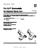
Instructions - Parts Pro Xp™ Electrostatic Air-Assisted Spray Gun 3A2495C For use in Class I, Div. I Hazardous Locations using Group D spray materials. For use in Group II, Zone 1 Explosive Atmosphere Locations using Group IIA spray materials. For professional use only. Important Safety Instructions Read all warnings and instructions in this manual. Save these instructions. 3000 psi (21 MPa, 210 bar) Maximum Fluid Working Pressure 100 psi (0.
Contents Models............................................................... 3 Warnings ........................................................... 4 Gun Overview .................................................... How the Electrostatic AA Spray Gun Works ............................................ Controls, Indicators, and Components ........... Smart Guns ................................................. 7 7 8 9 Installation.......................................................... 15 Warning Sign .
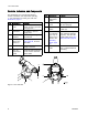
Models Models Part No. kV H60T10 60 H60M10 60 H85T10 85 H85M10 85 Smart Display Standard Display ✔ ✔ ✔ ✔ II 2 G EEx 0.
Warnings Warnings The following warnings are for the setup, use, grounding, maintenance and repair of this equipment. The exclamation point symbol alerts you to a general warning and the hazard symbol refers to procedure-specific risks. When these symbols appear in the body of this manual or on warning labels, refer back to these Warnings. Product-specific hazard symbols and warnings not covered in this section may appear throughout the body of this manual where applicable.
Warnings WARNING SKIN INJECTION HAZARD High-pressure fluid from gun, hose leaks, or ruptured components will pierce skin. This may look like just a cut, but it is a serious injury that can result in amputation. Get immediate surgical treatment. Do not spray without tip guard and trigger guard installed. Engage trigger lock when not spraying. Do not point gun at anyone or at any part of the body. Do not put your hand over the spray tip. Do not stop or deflect leaks with your hand, body, glove, or rag.
Warnings WARNING EQUIPMENT MISUSE HAZARD Misuse can cause death or serious injury. • Do not operate the unit when fatigued or under the influence of drugs or alcohol. • Do not exceed the maximum working pressure or temperature rating of the lowest rated system component. See Technical Data in all equipment manuals. • Use fluids and solvents that are compatible with equipment wetted parts. See Technical Data in all equipment manuals. Read fluid and solvent manufacturer’s warnings.
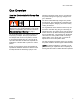
Gun Overview Gun Overview How the Electrostatic AA Spray Gun Works This is not an air spray gun. To help prevent serious injury from pressurized fluid, such as skin injection, and splashing fluid, read and follow the Skin Injection Hazard Warnings on page 5. The air-assisted spray gun combines airless and air spraying concepts. The spray tip atomizes and shapes the fluid into a fan pattern, as does a conventional airless spray tip.
Gun Overview Controls, Indicators, and Components The electrostatic gun includes the following controls, indicators, and components (see Fig. 1). For information on Smart guns, also see Smart Guns, page 9 . Item Description Purpose G Atomizing Air Adjustment Valve Adjusts atomizing air flow. Item Description Purpose H A Air Swivel Inlet 1/4 npsm(m) left-hand thread, for Graco grounded air supply hose. Trigger Safety Lock Locks trigger to prevent gun from spraying.
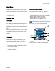
Gun Overview Smart Guns The Smart Gun module displays spraying voltage, current, alternator speed, and the voltage setting (low or high). It also allows the user to change to a lower spraying voltage. The module has two modes: Voltage Adjustment Switch • Operating Mode • The high voltage setting is determined by the maximum voltage of the gun and is not adjustable. • Diagnostic Mode Operating Mode Bar Graph See Fig. 2, and Table 1 on page 11.
Gun Overview Error Display If the Smart module loses communication with the power supply, the Error display appears, the Hz indicator turns red, and the Smart module is disabled. See Fig. 3, and Table 1 on page 11. This can occur in Operating Mode or Diagnostic Mode. See Electrical Troubleshooting, page 37. Communication must be restored to make the Smart module functional. for your gun. Continue pressing the button until you reach the desired setting.
Gun Overview Table 1 . Key for Figs. 2–9. Item Description Purpose VA Voltage Adjustment Switch Two-position switch sets smart gun voltage to low setting (LO) or high setting (HI). This switch is functional in Operating Mode and in Diagnostic Mode. LO Low Voltage Mode Indicator Lights (blue) when the smart gun is set to Low Voltage. kV Voltage (kV) Display Displays actual spraying voltage of the gun, in kV. In Operating Mode, display is a bar graph.
Gun Overview Item Description Purpose LD Lo Display Appears on the Low Voltage Lock Screen. See Fig. 9. ER Error Display Appears if the Smart module loses communication with the power supply. See Fig. 3. VI Voltage Indicator In Diagnostic Mode, the two top right LEDs of the screen light, indicating that the value displayed is in kV. See Fig. 6. CI Current Indicator In Diagnostic Mode, the two bottom right LEDs of the screen light, indicating that the value displayed is in uA. See Fig. 7.
Gun Overview Diagnostic Mode Diagnostic Mode includes four screens which display gun data: • Voltage (kiloVolts) Screen • Current (microAmperes) Screen • Alternator Speed (Hertz) Screen • Low Voltage Lock Screen NOTE: You must be in Operating Mode to adjust the low voltage setting; the setting is not adjustable in Diagnostic Mode. However, the voltage adjustment switch (VA) can be set to HI or LO in Operating Mode and in Diagnostic Mode.
Gun Overview Alternator Speed (Hertz) Screen Low Voltage Lock Screen The Alternator Speed (Hertz) Screen is the third screen in the Diagnostic Mode. See Fig. 8, and Table 1 on page 11. To enter this screen, press the LO SET button while in the Current (microAmperes) Screen. The Low Voltage Lock Screen is the fourth screen in the Diagnostic Mode. See Fig. 9, and Table 1 on page 11. To enter this screen, press the LO SET button while in the Alternator Speed (Hertz) Screen.
Installation Installation Warning Sign Installing and servicing this equipment requires access to parts which may cause electric shock or other serious injury if work is not performed properly. Mount warning signs in the spray area where they can easily be seen and read by all operators. An English Warning Sign is provided with the gun. Ventilate the Spray Booth • Do not install or service this equipment unless you are trained and qualified.
Installation Air Supply Line To reduce the risk of electric shock, the air supply hose must be electrically connected to a true earth ground. Use only Graco Grounded Air Supply Hose. 1. See Fig. 10. Use the Graco Grounded Air Supply Hose (AH) to supply air to the gun. The gun air inlet fitting has a left-hand thread. The air supply hose ground wire (AG) must be connected to a true earth ground. Do not connect the air supply hose to the gun air inlet yet. 2.
Installation NON-HAZARDOUS AREA HAZARDOUS AREA Figure 10 Typical Installation Typical Installation Key Item Description Item Description AF Air Filter/Water Separator FV Fluid Shutoff Valve AG* Gun Air Hose Ground Wire GR Gun Air Pressure Regulator AH* Graco Grounded Air Hose (left-hand threads) MA Main Air Supply Line AL Pump Air Line Lubricator PG* Pump Ground Wire BV* Pump Bleed-Type Air Shutoff Valve PR Pump Air Pressure Regulator EG Electrostatic Air Spray Gun RV Pump Runaw
Gun Setup Gun Setup Gun Setup Checklist See Fig. 11 to locate the electrostatic gun controls. 4. Connect the Graco grounded air hose to the gun air inlet. The gun air inlet fitting has left-hand threads. 5. Follow all steps under Grounding, page 21. 6. Follow all steps under Check Gun Electrical Grounding, page 25. Reading must be less than 1 megohm. Figure 11 Electrostatic Gun Controls 1. Turn OFF (O) the ES On-Off switch (J). 7.
Gun Setup 15. Check that the ES On-Off switch is OFF (O). To reduce the risk of a skin injection injury, always follow the Pressure Relief Procedure, page 27, before removing or installing the spray tip, air cap, or tip guard. 11. The fluid output and pattern width depend on the size of the spray tip, the fluid viscosity, and the fluid pressure. Use the Spray Tip Selection Chart, page 62, as a guide for selecting the appropriate spray tip for your application. 12.
Gun Setup 19. Check that the ES indicator (K) [Hz indicator on Smart guns] is lit. See the following table. 21. Turn the atomizing air adjustment valve counterclockwise until any tails disappear. Table 2 . LED Indicator Colors Indicator Color Description Green When spraying, the indicator should remain green, indicating sufficient air pressure to the alternator turbine. Amber If the indicator changes to amber after 1 second, the air pressure is too low.
Gun Setup Grounding • Object being sprayed: keep the workpiece hangers clean and grounded at all times. When operating the electrostatic gun, any ungrounded objects in the spray area (people, containers, tools, etc.) can become electrically charged. Improper grounding can result in static sparking, which can cause a fire, explosion, or electric shock. Ground all equipment, personnel, object being sprayed, and conductive objects in or close to the spray area. Resistance must not exceed 1 megohm.
Gun Setup • The floor of the spray area: must be electrically conductive and grounded. Do not cover the floor with cardboard or any non-conductive material which would interrupt grounding continuity • All persons entering the spray area: must wear shoes having conductive soles such as leather, or wear personal grounding straps. Do not wear shoes with non-conductive soles such as rubber or plastic. If gloves are necessary, wear the conductive gloves supplied with the gun.
Gun Setup Figure 12 Ground the Operator Figure 13 Ground the Object being Sprayed 3A2495C 23
Gun Setup Figure 14 Ground the Gun Figure 15 Ground the Fluid Supply 24 3A2495C
Gun Setup Check Gun Electrical Grounding 5. Make sure the grounded air hose is connected and the hose ground wire is connected to a true earth ground. Megohmmeter Part No. 241079 (AA-see Fig. 16) is not approved for use in a hazardous area.
Gun Setup Check Fluid Resistivity Check Fluid Viscosity To check fluid viscosity you will need: • a viscosity cup To reduce the risk of fire, explosion, or electric shock, check the fluid resistivity in a non-hazardous area only. Resistance Meter 722886 and Probe 722860 are not approved for use in a hazardous area. Failure to follow this warning could cause fire, explosion, or electric shock and result in serious injury and property damage. Graco Part No.
Operation Operation Pressure Relief Procedure 6. Engage the trigger lock. This equipment stays pressurized until pressure is manually relieved. To help prevent serious injury from pressurized fluid, such as skin injection, splashing fluid and moving parts, follow the Pressure Relief Procedure when you stop spraying and before cleaning, checking, or servicing the equipment. 7. Open the pump drain valve, having a waste container ready to catch the drainage.
Maintenance Maintenance Flushing • Flush before changing fluids, before fluid can dry in the equipment, at the end of the day, before storing, and before repairing equipment. 5. Point the gun into a grounded metal pail. Flush until clean solvent flows from the gun. • Flush at the lowest pressure possible. Check connectors for leaks and tighten as necessary. • Flush with a fluid that is compatible with the fluid being dispensed and the equipment wetted parts. 6. Follow the Pressure Relief Procedure, page 27.
Maintenance Clean the Gun Daily 1. Turn OFF (O) the ES On-Off switch. 6. Clean the outside of the gun with a compatible solvent. Use a soft cloth. Point the gun down to prevent solvent from entering the gun passages. Do not immerse the gun. 2. Follow the Pressure Relief Procedure, page 27. 3. Remove the air cap/tip guard and spray tip. 4. Flush the gun, see Flushing, page 28. 5. Follow the Pressure Relief Procedure, page 27.
Maintenance 7. Clean the air cap/tip guard and spray tip with a soft brush and compatible solvent. 9. Align the spray tip tab with the groove in the air cap. Install the tip. 10. Install the air cap and retaining ring. Orientate the air cap and tighten the retaining ring securely. 8. If necessary, use a toothpick or other soft tool to clean the air cap holes. Do not use metal tools.
Maintenance Daily System Care 5. Check the movement of the trigger and valves. Lubricate if necessary. 1. Follow the instructions under Clean the Gun Daily, page 29. Follow the Pressure Relief Procedure, page 27. 2. Clean the fluid and air filters. 6. Check Gun Electrical Grounding, page 25. 7. Hang the gun from its hook, with the nozzle pointing down. 3. Check for fluid leaks. Tighten all fittings. 4. Clean workpiece hangers. Use non-sparking tools.
Electrical Tests Electrical Tests Use the following procedures to test the condition of the power supply and gun body, and electrical continuity between components. NOTICE The gun body resistor cartridge is part of the body and is not replaceable. To avoid destroying the gun body, do not attempt to remove the body resistor. Use megohmmeter Part No. 241079 (AA) with an applied voltage of 500 V. Connect the leads as shown. Test Gun Resistance 1. Flush and dry the fluid passage. 2.
Electrical Tests Test Power Supply Resistance 6. Be sure the spring (11a) is in place before reinstalling the power supply. 1. Remove the power supply (11). See Power Supply Removal and Replacement, page 45. 2. Remove the alternator (15) from the power supply. See Alternator Removal and Replacement, page 46. 3. Measure resistance from the power supply's ground strips (EE) to the spring (11a). The resistance should be: • 86–110 megohms for 60kV guns • 130–160 megohms for 85kV guns 4.
Electrical Tests Test Gun Barrel Resistance 1. Insert a conductive rod (B) into the gun barrel (which was removed for the power supply test) and against the metal contact (C) in the front of the barrel. 2. Measure the resistance between the conductive rod (B) and the conductive ring (9). The resistance should be 10–30 megohms. If the resistance is incorrect, make sure the metal contact (C) in the barrel and the conductive ring (9) are clean and undamaged. 3.
Troubleshooting Troubleshooting Installing and servicing this equipment requires access to parts which may cause an electric shock or other serious injury if the work is not performed properly. Do not install or service this equipment unless you are trained and qualified. To reduce the risk of a skin injection injury, always follow the Pressure Relief Procedure, page 27, whenever you are instructed to relieve the pressure.
Troubleshooting Gun Operation Troubleshooting Problem Cause Solution Excessive spray fog. Atomizing air pressure too high. Close atomizing air valve part way, or decrease air pressure as low as possible; minimum 45 psi (0.32 MPa, 3.2 bar) needed at gun for full voltage. Fluid too thin. Increase viscosity or increase fluid flow rate. Atomizing air pressure too low. Open atomizing air valve more or increase gun air inlet pressure; use lowest air pressure necessary. Spray tip is too large.
Troubleshooting Electrical Troubleshooting Problem Cause Solution Poor wrap. ES On/Off switch is OFF (O). Turn ON (I). Gun air pressure too low (ES indicator is amber). Check air pressure to gun; minimum 45 psi (0.32 MPa, 3.2 bar) needed at gun for full voltage. Atomizing air pressure too high. Decrease. Fluid pressure too high. Decrease, or replace worn tip. Incorrect distance from gun to part. Should be 8-12 in. (200-300 mm). Poorly grounded parts. Resistance must be 1 megohm or less.
Troubleshooting Problem Cause Solution Voltage/current display stays red (smart guns only). Gun is too close to the part being sprayed. Gun should be 8–12 in. (200–300 mm) from the part. Check fluid resistivity. See Check Fluid Resistivity, page 26. Dirty gun. See Clean the Gun Daily, page 29. ES or Hz indicator is amber. Alternator speed is too low. Increase air pressure until indicator is green.
Repair Repair Prepare the Gun for Service • Use a vise with padded jaws to prevent damage to plastic parts. Installing and repairing this equipment requires access to parts that may cause electric shock or other serious injury if the work is not performed properly. Do not install or service this equipment unless you are trained and qualified. • Lubricate the some needle assembly parts (20) and certain fluid fittings with dielectric grease (57), as specified in the text.
Repair Air Cap, Spray Tip, and Fluid Seat Housing Replacement 1. See Prepare the Gun for Service, page 39. 2. Remove the retainer ring (22) and air cap/tip guard assembly (25). 4. To replace the electrode (25a), see Electrode Replacement, page 41. The conductive ring (9) is a conductive metal contact ring, not a sealing o-ring. To reduce the risk of fire, explosion, or electric shock: • Do not remove the conductive ring except to replace it. • Never operate the gun without the conductive ring in place.
Repair NOTICE Do not overtighten the fluid seat housing (24). Overtightening may damage the housing and the gun barrel, resulting in improper fluid shutoff. 6. Trigger the gun and install the fluid seat housing (24). Tighten until snug, then 1/4 turn more. 7. Check that the spray tip gasket (27a) is in place. Align the spray tip tab with the groove in the air cap (25). Install the spray tip (27) in the air cap. 8. Make sure that the electrode (25a) is installed correctly in the air cap. 9.
Repair Fluid Tube Removal and Replacement Fluid Filter Replacement 1. See Prepare the Gun for Service, page 39. 1. See Prepare the Gun for Service, page 39. 2. Disconnect the bottom fluid tube nut (C). 2. Disconnect the bottom fluid tube nut (C). 3. Carefully unscrew the top fluid tube nut (D). 3. Remove the fluid filter (10) from the fluid fitting. Clean or replace the filter, as needed.
Repair Gun Barrel Removal Gun Barrel Installation 1. See Prepare the Gun for Service, page 39. 1. Be sure the gasket (5*) and grounding spring (37a) are in place. Make sure the gasket air holes are aligned properly. Replace the gasket if damaged. 2. Disconnect the bottom fluid tube nut (N). Carefully separate the tube assembly (T) from the bracket (7). 3. Loosen the two screws (6). NOTICE To avoid damaging the power supply (11), pull the gun barrel straight away from the gun handle.
Repair Fluid Needle Replacement 1. See Prepare the Gun for Service, page 39. 2. Remove the air cap assembly and fluid seat housing. See Air Cap, Spray Tip, and Fluid Seat Housing Replacement, page 40. 3. Remove the gun barrel. See Gun Barrel Removal, page 43. 4. Remove the trigger screws (13) and trigger (12). 5. Unscrew the spring cap (37). Remove the spring (20a). 6. Insert the supplied driver (60) in the socket at the back of the fluid needle. Press forward so the two segments of the needle engage (R).
Repair Power Supply Removal and Replacement • Inspect the gun handle power supply cavity for dirt or moisture. Clean with a clean, dry rag. • Do not expose gasket (5) to solvents. 1. See Prepare the Gun for Service, page 39. 2. See Gun Barrel Removal, page 43. (EE) make contact with the handle. On Smart models, align the connector of the 6–pin flexible circuit (40) with the socket (CS) at the top of the handle.
Repair Alternator Removal and Replacement NOTE: Replace alternator bearings after 2000 hours of operation. Order Part No. 24N706 Bearing Kit. Parts included in the kit are marked with a symbol (♦). 1. See Prepare the Gun for Service, page 39. 2. Remove the power supply/alternator assembly and disconnect the alternator. See Power Supply Removal and Replacement, page 45. 3. Measure resistance between the two outer terminals of the 3-wire connector (PC); it should be 2.0–6.0 ohms.
Repair 12. Hold the coil assembly (15a) on a workbench with the fan end facing up. Press the fan (15e♦) onto the long end of the shaft (S). The fan blades must be oriented as shown. 13. Carefully press the coil assembly (15a) into the front of the housing (15d♦). The 3–wire connector (PC) must be positioned below the wider notch (W) of the housing tabs, as shown in Fig. 35. Be sure the coil alignment pins (P) are positioned as shown in Fig. 34. 14.
Repair Fan Air Adjustment Valve Repair 1. See Prepare the Gun for Service, page 39. 2. Place a wrench on the flats of the valve assembly (30) and unscrew it from the handle (16). NOTE: You may replace the valve as an assembly (go to step 9) or as individual parts (steps 3-9). 8. Reassemble the retaining ring (30d). Unscrew the valve stem from the housing until it is stopped by the retaining ring. 9. Screw the valve assembly (30) into the gun handle (16), using a wrench on the flats of the housing.
Repair Atomizing Air Adjustment Valve Repair 1. See Prepare the Gun for Service, page 39. 2. Place a wrench on the flats of the valve assembly (29) and unscrew it from the handle (16). 3. Inspect the valve assembly. If damaged, install a new valve (29). 4. Before installing the valve assembly in the handle, unscrew the valve stem (29b) from the housing (29a) until it stops. Figure 38 Atomizing Air Adjustment Valve 5. Install the valve assembly into the gun handle.
Repair ES On-Off Valve Repair 1. See Prepare the Gun for Service, page 39. 2. Loosen the captive screw (26p). Remove the valve (26) from the handle. 3. Lubricate the o-rings (26b* and 26g*) with non-silicone grease, Part No. 111265. Do not over-lubricate. 4. Clean and inspect parts for damage. Replace if necessary. NOTE: The protrusion on the retainer plate (26f) must point upward. 5. Reinstall the valve. Torque the screw (26p) to 15-25 in-lb (1.7-2.8 N•m). NOTE: Do not over-lubricate parts.
Repair Air Valve Repair 1. See Prepare the Gun for Service, page 39. 2. See Gun Barrel Removal, page 43. 3. Remove the screws (13) and trigger (12). 4. Remove the ES On-Off Valve. See ES On-Off Valve Repair, page 50. 5. Remove the spring (2). 8. Install the air valve (23) and spring (2) into the gun handle (16). 9. Install the ES On-Off Valve. See ES On-Off Valve Repair, page 50. 10. Install the trigger (12) and screws (13). 11. See Gun Barrel Installation, page 43. 6.
Repair Smart Module Replacement If the Error display appears, the Smart Module has lost communication with the power supply. Check for good connections between the Smart Module and the power supply. If the module’s LEDs are not lighting, replace the module. 1. See Prepare the Gun for Service, page 39. 2. Remove the pivot screw (31e), o-ring (31f), and ES HI/LO switch (31c) at the bottom left corner of the Smart Module cartridge (31a). 3. Remove the remaining three screws (31d) from the cartridge. 4.
Repair Air Swivel and Exhaust Valve Replacement 1. See Prepare the Gun for Service, page 39. 2. To replace the air exhaust valve: a. Remove the clamp (36) and the exhaust tube (35). b. Unscrew the swivel (21) from the gun handle (16). The swivel is a left-hand thread. Remove the bracket (7). c. Pull the exhaust valve (8) from the handle (16). Inspect the o-ring (8a) and replace if necessary. d. Install the o-ring (8a*) on the exhaust valve (8).
Parts Parts Standard Air-Assisted Spray Gun Assembly Part No. H60T10 60 kV Electrostatic Air-Assisted Spray Gun, Series A Part No.
Parts Part No. H60T10 60 kV Electrostatic Air-Assisted Spray Gun, Series A Part No. H85T10 85 kV Electrostatic Air-Assisted Spray Gun, Series A Ref. No. 1 Part No.
Parts Smart Air-Assisted Spray Gun Assembly Part No. H60M10 60 kV Electrostatic Air-Assisted Spray Gun, Series A Part No.
Parts Part No. H60M10 60 kV Electrostatic Air-Assisted Spray Gun, Series A Part No. H85M10 85 kV Electrostatic Air-Assisted Spray Gun, Series A Ref. No. 1 Part No.
Parts Alternator Assembly Part No. 24N664 Alternator Assembly Ref. No. Part No. Description Qty Ref. No. Part No.
Parts ES On-Off Valve Assembly Part No. 24N632 ES On-Off Valve Assembly Ref. No. Part No. Description Qty Ref. No. Part No. Description Qty 26a ——— HOUSING, valve 1 26e ——— SCREW, set, socket head 2 26b* 15D371 O-RING 2 26f 24N631 PLATE, retaining 1 26c ——— PISTON, valve 1 26g* 113746 O-RING 1 26d 24N650 LEVER, ES on-off; includes item 26e 1 26p ——— SCREW, captive 1 * These parts are included in Air Seal Repair Kit 24N789 (purchase separately).
Parts Fan Air Valve Assembly Part No. 24N634 Fan Air Valve Assembly Ref. No. Part No. Description Qty 30a ——— NUT, valve 1 30b ——— STEM, valve 1 30c* 111504 O-RING 1 30d 24N646 RING, retaining; package of 6 1 * These parts are included in Air Seal Repair Kit 24N789 (purchase separately). Parts labeled — — — are not available separately.
Parts Air Cap Assembly Smart Module Assembly Part No. 24N727 Air Cap Assembly Part No. 24N756 Smart Module Assembly Ref. No. Part No. Description Qty 25a 24N643 ELECTRODE; package of 5 1 25b 24N734 O-RING; ptfe; package of 5 (also available in package of 10; order 24E459) 1 25c ——— AIR CAP 1 25d 24N726 GUARD, tip, orange 1 Parts labeled — — — are not available separately. Ref. No. Part No.
Spray Tip Selection Chart Spray Tip Selection Chart AEM Fine Finish Spray Tips Recommended for high finish quality applications at low and medium pressures. Order desired tip, Part No. AEMxxx, where xxx = 3–digit number from the matrix below. Orifice Size in. (mm) Fluid Output fl oz/min (l/min) at 1000 at 600 psi (4.1 psi (7.0 MPa, MPa, 41 bar) 70 bar) † 0.007 4.0 (0.178) (0.1) † 0.009 7.0 (0.229) (0.2) † 0.011 10.0 (0.279) (0.3) 13.0 0.013 (0.330) (0.4) 0.015 17.0 (0.381) (0.5) 0.017 22.0 (0.432) (0.7) 28.
Spray Tip Selection Chart AEF Fine Finish Pre-Orifice Spray Tips Recommended for high finish quality applications at low and medium pressures. AEF tips have a pre-orifice that assists in atomizing sheer thinning materials, including lacquers. Order desired tip, Part No. AEFxxx, where xxx = 3–digit number from the matrix below. Orifice Size in. (mm) Fluid Output fl oz/min (l/min) Maximum Pattern Width at 12 in. (305 mm) in. (mm) at 600 psi (4.1 MPa, 41 bar) at 1000 psi (7.0 MPa, 70 bar) † 0.010 (0.254) 9.
Repair Kits, Related Manuals, and Accessories Repair Kits, Related Manuals, and Accessories Gun Part No. Description Manual Description Repair Kits Repair Kit Description All guns in this manual. 60 kV and 85 kV Air-Assisted Spray Guns Electrostatic Air-Assisted Spray Guns, Instructions-Parts 24N789 Air Seal Repair Kit 24N706 Alternator Bearing Repair Kit System Accessories Gun Accessories Part No. Description 105749 Cleaning Brush. 111265 Non-silicone Lubricant, 4 oz (113 g).
Repair Kits, Related Manuals, and Accessories Hoses Grounded Air Hoses Air Whip Hoses 100 psi (0.7 MPa, 7 bar) Maximum Working Pressure 100 psi (0.7 MPa, 7 bar) Maximum Working Pressure 0.315 in. (8 mm) ID; 1/4 npsm(f) x 1/4 npsm(f) left-hand thread 0.188 in. (5 mm) ID; 1/4 npsm(m) x 1/4 npsm(f) left-hand thread Part No. Description AirFlex Flexible Grounded Air Hose (Gray) Part No. Description Air Whip Hose with stainless steel braid ground path (Red) 244963 6 ft (1.8 m) 244964 15 ft (4.
Dimensions Dimensions Figure 45 Gun Model A, in. (mm) B, in. (mm) C, in. (mm) Weight, oz (g) H60T10 9.7 (246) 9.1 (231) 2.4 (61) 23.2 (659) H85T10 10.7 (272) 9.2 (234) 2.4 (61) 25.8 (732) H60M10 9.8 (249) 9.9 (251) 2.4 (61) 25.7 (728) H85M10 10.8 (274) 9.9 (251) 2.4 (61) 28.
Technical Data Technical Data Electrostatic Air-Assisted Spray Guns U.S. Metric Maximum Working Fluid Pressure 3000 psi 21 MPa, 210 bar Maximum Working Air Pressure 100 psi 0.7 MPa, 7.0 bar Minimum Air Pressure at Gun Inlet 45 psi 0.32 MPa, 3.
Graco Pro Xp Warranty Graco warrants all equipment referenced in this document which is manufactured by Graco and bearing its name to be free from defects in material and workmanship on the date of sale to the original purchaser for use. With the exception of any special, extended, or limited warranty published by Graco, Graco will, for a period of twelve months from the date of sale, repair or replace any part of the equipment determined by Graco to be defective.