Instructions - Parts 24P822 E-Flo® DC Control 3A2527D Module Kit EN User Interface for E-Flo® DC Pumps with an Advanced Motor. For professional use only. Important Safety Instructions Read all warnings and instructions in this manual, the supplied ADCM manual, and the E-Flo DC manuals. Save these instructions. See the separate manual (supplied) for complete warnings and approvals information about the 24L097 Advanced Display Control Module (ADCM). PROVEN QUALITY. LEADING TECHNOLOGY.
Contents Control Module ................................................... 3 Installation.......................................................... Install the Control Module ............................. Install Optional Accessory Kits ...................... Cable Connection ........................................ 3 3 4 5 Operation ........................................................... Module Screens........................................... Module Keys............................................
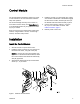
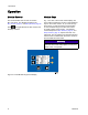
Control Module Control Module The Control Module provides the interface for users to enter selections and view information related to setup and operation. The screen backlight is factory set to remain on, even without screen activity. See Setup Screen 4 to set the backlight timer to your preference. Press any key to restore. Keys are used to input numerical data, enter setup screens, navigate within a screen, scroll through screens, and select setup values. 4.
Installation Install Optional Accessory Kits Optional accessory kits are available for purchase separately, including a pressure transducer kit (PN 24R050), a start/stop switch kit (PN 16U729), and a controller kit (24V001 ) for a back pressure regulator. Pressure Transducer Kit 1. To measure fluid pressure, install the pressure transducer in the fluid line with a tee fitting.
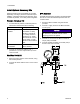
Installation Cable Connection Order an accessory cable (C) from Table 1. Connect the cable to Port 3 on the bottom of the control module (see Fig. 2). Connect the other end to the power terminal (PT) on the motor (see Fig. 3). Connect other cables as described in Table 2. Table 1 CAN Cables Cable Part No.
Operation Operation Module Screens Module Keys The Control Module has two sets of screens: Run and Setup. For detailed information see Run Screens, page 12, and Setup Screens, page 16. Fig. 4 is a view of the control module display and keys. Table 2 explains the function of the membrane keys on the control module. As you move through the screens, you will notice that most information is communicated using icons rather than words to simplify global communication.
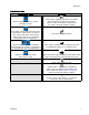
Operation Table 3 Module Keys Membrane Keys Softkeys Enter Screen. Highlight data that can be edited. Press to toggle between Run screens and Setup screens. Also changes the function of the Up/Down arrows so they move between data fields on the screen, rather than between screens. Error Reset: Use to clear alarm after cause has been fixed. When there is no alarm to clear, this key will set the active pump’s profile to Stop. Also used to cancel data entered and return to original data. Exit Screen.
Operation Icons As you move through the screens, you will notice that most information is communicated using icons rather than words to simplify global communication. The detailed screen descriptions in Run Screens, page 12, and Setup Screens, page 16, explain what each icon represents.
Operation Screen Navigation and Editing Refer to this section if you have questions about screen navigation or about how to enter information and make selections. All Screens 1. Use to move between screens. 2. Press to enter a screen. The first data field on the screen will highlight. 3. Use change. 4. Press to highlight the data you wish to to edit. Drop Down Field to highlight the correct choice from 1. Use the dropdown menu. 2. Press 3. Press to select.
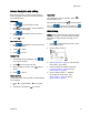
Screen Map Screen Map INITIAL SETUP (Setup Screens 5–14) SETUP AND EDIT PROFILES (Setup Screens 1–4) RUN (Run Screens 1–8) Setup Screen 5, page 22 Setup Screen 1, page 16 Run Screen 1, page 12 Setup Screen 6, page 23 Setup Screen 2, page 18 Run Screen 2, page 13 Setup Screen 7, page 23 Setup Screen 3, page 19 Run Screen 3, page 13 Setup Screens 8 and 9, page 24 Setup Screen 4, page 20 Run Screen 4, page 14 Setup Screens 10 and 11, page 25 Run Screens 5–8, page 14 CONTINUED ON THE NEXT PAGE
Screen Map INITIAL SETUP (Setup Screens 5–14) SETUP AND EDIT PROFILES (Setup Screens 1–4) RUN (Run Screens 1–8) Setup Screen 12, page 26 Setup Screen 13, page 27 Setup Screen 14, page 28 Setup Screen 15, page 29 3A2527D 11
Run Screens Run Screens The Run screens display current target values and performance for a selected pump and profile. Any alarms will display in the sidebar at the right of the screen. Screens 5–8 display a log of the last 20 alarms for the active pump. Information displayed on the Run screens corresponds to the Modbus Registers. See Appendix A - Modbus Variable Map, page 34. The active pump and profile may be changed in Run Screens 1, 2, and 3.
Run Screens Run Screen 2 Run Screen 3 This screen displays pressure settings for the active pump and profile. This screen displays fluid flow settings for the active pump and profile. NOTE: Some fields are grayed out, depending on setup selections. NOTE: Some fields are grayed out, depending on setup selections.
Run Screens Run Screen 4 Run Screens 5–8 This screen displays the current pressure readings of transducers 1 and 2. Pressure can be displayed as psi, bar, or MPa. See Setup Screen 13, page 27. Run Screens 5–8 display a log of the last 20 alarms, with date and time. The currently active pump is displayed in a box at the top left of the screen.
Notes Notes 3A2527D 15
Setup Screens Setup Screens Use the Setup screens to set control parameters for the motor. See Screen Navigation and Editing, page 9 , for information on how to make selections and enter data. Setup Screen 1 Key Enter the screen. Pump selection — See Step 1. Inactive fields are grayed-out on a screen. Profile selection — See Step 2. Information displayed on the Setup screens corresponds to the Modbus Registers. See Appendix A - Modbus Variable Map, page 34.
Setup Screens 1. For systems with multiple pumps and one display, select the desired pump (1 to 8), using the pull-down menu. • In flow mode, the motor will maintain a constant speed to maintain the target flow rate set on Setup Screen 3, regardless of the fluid pressure, up to the pump’s maximum working pressure. Figure 15 Select Pump Number 2. Select the desired profile (1 to 4), using the pull-down menu. Figure 17 Select Mode (Pressure Mode Shown) 4.
Setup Screens Setup Screen 2 Use this screen to set the maximum, target, and minimum fluid pressure for a selected pump and profile. In pressure mode, you will set a target fluid pressure. In flow mode, you will set a maximum fluid pressure. In either pressure or flow mode, a minimum pressure may be set if desired. See Setup Screen 4, page 20, to specify how the system will respond if the pump begins to operate outside of the set boundaries. Setup Screen 2 Key Enter the screen. 1.
Setup Screens Setup Screen 3 Use this screen to set your flow rate settings for a selected pump and profile. In pressure mode, you will set a maximum flow rate. In flow mode, you will set a target flow rate. In either pressure or flow mode, a minimum flow rate may be set if desired. See Setup Screen 4 to specify how the system will respond if the pump begins to operate outside of the set boundaries. 1. For systems with multiple pumps and one display, select the desired pump (1 to 8), using the pull-down menu. 2.
Setup Screens Setup Screen 4 Use this screen to specify how the system will respond if the pump begins to operate outside of the pressure and flow settings established on Setup Screen 2 and Setup Screen 3. The operating mode (pressure or flow, set on Setup Screen 1) determines which fields are active. Setup Screen 4 Key Enter the screen to set or change preferences. Pressure Alarm Enable Line 1 (Pressure Maximum): use dropdown menu to set as Limit, Deviation, or Alarm.
Setup Screens Pressure Mode Examples Flow Mode Examples • Runaway Control: The user may choose to set the maximum flow to Alarm. If the flow rate exceeds the maximum entered on Setup Screen 3, an Alarm symbol will show on screen and the pump will shut down. • Runaway Control: The user may choose to set the minimum pressure to Alarm. If a hose bursts, the pump will not change speed, but the back pressure will fall.
Setup Screens Setup Screen 5 Use this screen to set the lower pump size (cc) of each pump. The default is blank; select the correct lower size, or custom. If custom is selected, enter the size of the lower in cc. This screen also activates jog mode, allowing you to position the motor/pump shaft for connection or disconnection. NOTE: The motor will limit its pressure output when the selected lower is 750cc, to prevent exceeding the pressure rating of the lower.
Setup Screens Setup Screen 6 Setup Screen 7 Use this screen to view the grand totalizer value and set or reset the batch totalizer. Use this screen to set the desired maintenance interval (in cycles) for each pump. The screen also displays the current cycle count. An Advisory is issued when the counter reaches 0 (zero). Figure 28 Setup Screen 6 Figure 30 Setup Screen 7 Setup Screen 7 Key Enter the screen. Figure 29 Reset the Totalizer Setup Screen 6 Key Enter the screen to set or change preferences.
Setup Screens Setup Screens 8 and 9 Use these screens to set up the pressure transducers. The screens are identical, except Screen 8 is for transducer 1 and Screen 9 is for transducer 2. Selecting a transducer and a pump activates closed loop pressure control. Figure 31 Setup Screens 8 and 9 (Screen 8 shown) Setup Screens 8 and 9 Key Figure 32 Select Pressure Transducer Figure 33 Select Pump, to Enable Closed Loop Pressure Control Select from the dropdown options to enable the transducer.
Setup Screens Setup Screens 10 and 11 These screens are auto-populated by the software. Screen 10 displays the serial numbers of motors 1–4, and Screen 11 displays the serial numbers of motors 5–8. NOTE: Changing the pump order will shift every other pump up one position. For example, if AD00001 is changed to be pump 4, AD00002 will become pump 1, AD00003 will become pump 2, and so on.
Setup Screens Setup Screen 12 Use this screen to set your modbus preferences. Figure 40 Set Modbus Node ID Figure 38 Setup Screen 12 Setup Screen 12 Key Enter the screen. For systems with multiple pumps and one display, select the desired pump (1 to 8), using the pull-down menu. Control location. Select local or remote control from the dropdown options. Setting applies to the selected pump only. Enter or change the Modbus node ID. Value is between 1 and 247.
Setup Screens Setup Screen 13 Use this screen to set the desired units for pressure, totals, and flow. Figure 43 Select Desired Pressure Units Figure 42 Setup Screen 13 Setup Screen 13 Key Select desired pressure units (psi, bar, or MPa) Select desired volume units (liters or gallons) Figure 44 Select Desired Volume Units Select desired flow rate units (L/min, gpm, cc/min, oz/min, or cycles/min) Exit data editing.
Setup Screens Setup Screen 14 Use this screen to set your date format, date, and time. Figure 47 Select the Date Format Figure 46 Setup Screen 14 Setup Screen 14 Key Enter the screen to set or change preferences. Select your preferred date format from the dropdown menu. Figure 48 Set the Date MM/DD/YY DD/MM/YY YY/MM/DD Set the correct date. Set the correct time. Figure 49 Set the Time Press to accept the selections. Exit data editing.
Setup Screens Setup Screen 15 Use this screen to enter a password that will be required to access the Setup screens. This screen also displays the software version. Figure 51 Set the Password Figure 50 Setup Screen 15 Setup Screen 15 Key Enter the screen to set the password. When the top box of the screen is checked, the password is active. To temporarily disable the password, uncheck the box. The password field will be grayed-out. Figure 52 Disable the Password Enter the desired 4–digit password.
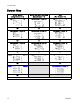
Error Code Troubleshooting Error Code Troubleshooting Error codes can take three forms: • Alarm : alerts you to the alarm cause and shuts down the pump. • Deviation : alerts you to the problem, but pump may continue to run past the set limits until the system’s absolute limits are reached. • Advisory: information only. Pump will continue to operate. NOTE: On Advanced motors, flow (K codes) and pressure (P codes) can be designated as alarms or deviations. See Setup Screen 4, page 20.
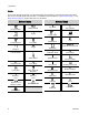
Error Code Troubleshooting Display Code Applicable Motor Blink Code Alarm or Deviation MND_ Advanced None Advisory Maintenance counter is enabled and countdown reached zero (0). P1I_ Advanced 1–3 P2I_ Advanced None Deviation Pressure is below minimum limit. P3I_ Advanced None Deviation Pressure exceeds maximum target. P4I_ Advanced 1–4 P5DX Advanced None Deviation More than one pump is assigned to a transducer.
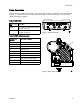
Parts Parts 24P822 Control Module Kit Ref Part Description Qty Ref 1 24P821 DISPLAY KIT, control module; includes item 1a; see manual 332013 for approvals information about the bare ADCM module LABEL, warning, English LABEL, warning, French LABEL, warning, Spanish (shipped loose) CONNECTOR, jumper; includes item 5a SCREW, cap, socket head; M5 x 40 mm BRACKET KIT, control module; includes items 6a-6f 1 6a Part ——— 6b ——— 6c ——— 6d ——— 6e ——— 6f 1a▲ 16P265 1b▲ 16P265 1c▲ 16P265 5
Parts Accessory Kits BPR Controller Kit 24V001 Ref 101 Part ——— Description Qty Ref Part Description Qty 1 106 110207 ELBOW 1 107 C19466 TEE 1 108 198171 ELBOW 1 102 ——— TRANSDUCER, miniature CABLE, F/C, I.S., 8 M 103 110436 GAUGE, pressure, air 1 104 100030 BUSHING 1 105 198178 ELBOW 1 1 ——— Parts not sold separately. Start/Stop Switch Kit 16U729 The kit includes the switch and enclosure, a mounting bracket, and cables. Parts are not sold separately.
Appendix A - Modbus Variable Map Appendix A - Modbus Variable Map To communicate through fiber optics with the E-Flo DC Control Module, reference the appropriate hardware as shown in manual 332356. That manual indicates various options for connecting fiber optic cables from the control module to the non-hazardous area. The following table lists Modbus registers available to a PC or PLC located in the non-hazardous area.
Appendix A - Modbus Variable Map NOTE: See Error Code Troubleshooting, page 30, for a description of each alarm.
Appendix A - Modbus Variable Map 404114 - Display Alarms Word 1 Bit 1 Event Type Deviation Event Code Event Name P6C_ Pressure Transducer Missing others Reserved 404115 - Display Alarms Word 2 Bit Event Type Event Code Event Name 12 Alarm CAG_ Modbus Communication 15 Alarm CAC_ CAN Communication Display others Reserved Table 6 Pump Status and Control Bits 404100 - Pump Status Bits Bit Meaning 0 Reads 1 if the pump is trying to move 1 Reads 1 if the pump is actually moving 2 Read
Appendix A - Modbus Variable Map Table 7 Units Unit Type Selectable Units Units Register Converting registers to unit values Register value for 1 unit Pressure Percent n/a Pressure = Register 1 = 1% Pressure Pressure psi 403208 = 0 Pressure = Register 1 = 1 psi Bar 403208 = 1 Pressure = Register/10 10 = 1.0 Bar MPa 403208 = 2 Pressure = Register/100 100 = 1.00 Mpa Speed Cycles/min n/a Speed = Register/10 10 = 1.0 cycle/min Flow Liters/min 403210 = 0 Flow = Register/10 10 = 1.
Appendix B. Pump Control from a PLC Appendix B. Pump Control from a PLC This guide shows how to use the information in Appendix A to control a pump remotely from a PLC. The steps progress from basic pump control to more advanced monitoring and alarm control features. It is important that you first follow all directions in the Setup Screens to configure your system properly. Test that the pump operates correctly when controlled from the Display.
Notes Notes 3A2527D 39
Graco Standard Warranty Graco warrants all equipment referenced in this document which is manufactured by Graco and bearing its name to be free from defects in material and workmanship on the date of sale to the original purchaser for use. With the exception of any special, extended, or limited warranty published by Graco, Graco will, for a period of twelve months from the date of sale, repair or replace any part of the equipment determined by Graco to be defective.