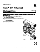
Repair/Parts Husky™ 2200 Air-Operated Diaphragm Pump 3A2714B Polypropylene or PVDF pumps for fluid transfer applications, including high viscosity materials. For professional use only. Not for use in European explosive atmosphere locations. Important Safety Instructions Read all warnings and instructions in this manual and in your Operation manual. Save these instructions. Maximum Working Pressure: 125 psi (0.86 MPa, 8.6 bar) PROVEN QUALITY. LEADING TECHNOLOGY.
Contents Warnings ........................................................... 3 Ordering Information ........................................... 6 Related Manuals ................................................ 6 Configuration Number Matrix ............................... 7 Troubleshooting.................................................. 8 Notes................................................................. 10 Repair................................................................
Warnings Warnings The following warnings are for the setup, use, grounding, maintenance, and repair of this equipment. The exclamation point symbol alerts you to a general warning and the hazard symbols refer to procedure-specific risks. When these symbols appear in the body of this manual or on warning labels, refer back to these Warnings. Product-specific hazard symbols and warnings not covered in this section may appear throughout the body of this manual where applicable.
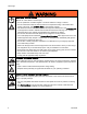
Warnings WARNING EQUIPMENT MISUSE HAZARD Misuse can cause death or serious injury. • Do not operate the unit when fatigued or under the influence of drugs or alcohol. • Do not exceed the maximum working pressure or temperature rating of the lowest rated system component. See Technical Data in all equipment manuals. • Use fluids and solvents that are compatible with equipment wetted parts. See Technical Data in all equipment manuals. Read fluid and solvent manufacturer’s warnings.
Warnings WARNING TOXIC FLUID OR FUMES HAZARD Toxic fluids or fumes can cause serious injury or death if splashed in the eyes or on skin, inhaled, or swallowed. • Read MSDSs to know the specific hazards of the fluids you are using. • Route exhaust away from work area. If diaphragm ruptures, fluid may be exhausted into the air. • Store hazardous fluid in approved containers, and dispose of it according to applicable guidelines.
Ordering Information Ordering Information To Find Your Nearest Distributor Distributor Note 1. Visit www.graco.com. 1. To find part numbers for new pumps or kits, use the Online Husky Selector Tool. 2. Click on Where to Buy and use the Distributor Locator. To Specify the Configuration of a New Pump Please call your distributor. OR Use the Online Husky Selector Tool on the Process Equipment page at www.graco.com. To Order Replacement Parts Please call your distributor. 2.
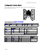
Configuration Number Matrix Configuration Number Matrix Check the identification plate (ID) for the Configuration Number of your pump. Use the following matrix to define the components of your pump.
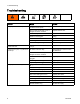
Troubleshooting Troubleshooting Problem Cause Solution Pump cycles but will not prime. Pump is running too fast, causing cavitation before prime. Reduce air inlet pressure. Check valve ball severely worn or wedged in seat or manifold. Replace ball and seat. Seat severely worn. Replace ball and seat. Outlet or inlet clogged. Unclog. Inlet or outlet valve closed. Open. Inlet fittings or manifolds loose. Tighten. Manifold o-rings damaged. Replace o-rings.
Troubleshooting Problem Cause Solution Air bubbles in fluid. Suction line is loose. Tighten. Diaphragm (or backup) ruptured. Replace. Loose manifolds, damaged seats or o-rings. Tighten manifold bolts or replace seats or o-rings. Pump cavitation. Reduce pump speed or suction lift. Loose diaphragm shaft bolt. Tighten. Exhaust air contains fluid being pumped. Diaphragm (or backup) ruptured. Replace. Loose diaphragm shaft bolt. Tighten or replace. Moisture in exhaust air.
Notes Notes 10 3A2714B
Repair Repair Pressure Relief Procedure Follow the Pressure Relief Procedure whenever you see this symbol. 4. Align the new air valve gasket (105*) on the center housing, then attach the new air valve. Follow the Torque Instructions, page 19. 5. Reconnect the air line to the motor. This equipment stays pressurized until pressure is relieved manually.
Repair Replace Seals or Rebuild Air Valve Follow these instructions to service the air valve with one of the available repair kits. Air Valve Seal Kit parts are marked with a †. Air Valve Repair Kit parts are marked with a ♦. Air Valve End Cap Kit parts are marked with a ‡. Disassemble the Air Valve 2. Grease the u-cups (208♦†) and install on the piston with lips facing toward the center of the piston. Lips face down. 1. Perform steps 1-3 under Replace Complete Air Valve, page 11. 2.
Repair 6. Install the o-ring (214♦) on the cup (213♦). Apply a light film of grease to the outside surface of the o-ring and the inside mating surface of the base (212♦). Orient the end of the base that has a magnet toward the end of the cup that has the larger cutout. Engage the opposite end of the parts. Leave the end with the magnet free. Tilt the base toward the cup and fully engage the parts, using care so that the o-ring remains in place.
Repair Check Valve Repair NOTE: Kits are available for new check valve balls and seats in a range of materials. See page 27 to order kits in the material(s) desired. O-ring and fastener kits also are available. NOTE: To ensure proper seating of the check balls, always replace the seats when replacing the balls. Also, replace the o-rings every time the manifold is removed. Disassemble the Check Valve 1. Follow the Pressure Relief Procedure, page 11. Disconnect all hoses. NOTE: The pump is heavy.
Repair Diaphragm and Center Section Repair 4. All Other Diaphragms NOTE: Diaphragm kits are available in a range of materials and styles. See pages 28 – 29. A Center Rebuild Kit also is available. See page 23. Parts included in the Center Rebuild Kit are marked with an *. For best results, use all kit parts. Disassemble the Diaphragm and Center Section 1. Follow the Pressure Relief Procedure, page 11. 2.
Repair Reassemble the Diaphragm and Center Section Follow all notes in the illustration. These notes contain important information. NOTE: Apply lithium-based grease whenever instructed to grease. 1. Clean all parts and inspect for wear or damage. Replace parts as needed. 2. If removed, grease and install the new pilot valve cartridges (109), cartridge o-rings (110), and retaining rings (113). NOTE: Cartridges (109) must be installed before pilot valves (111). 3. Grease and install the pilot valves (111).
Repair SP and FK Models PO Models PT Models Rounded side faces diaphragm Apply lithium based grease. Apply primer and medium-strength (blue) thread locker. Torque to 100-105 ft-lb (136–142 N•m). AIR SIDE markings on diaphragm must face center housing. If screw comes loose or is replaced, apply permanent (red) thread locker to diaphragm side threads. Apply primer and medium-strength (blue) thread locker to shaft side threads. Lips must face out of housing.
Repair 8. To ensure proper seating and extend diaphragm life, apply air pressure to the pump prior to attaching the second fluid cover. a. Place the supplied tool (302) where the air valve gasket (105) normally goes. Arrows (A) must face toward the fluid cover that is already attached. c. Supply a minimum of 20 psi (0.14 MPa, 1.4 bar) air pressure to the air valve. Shop air may be used. The diaphragm will shift so the second fluid cover will seat properly.
Torque Instructions Torque Instructions If fluid cover or manifold fasteners have been loosened, it is important to torque them using the following procedure to improve sealing. Inlet and Outlet Manifold Screws NOTE: Fluid cover and manifold fasteners have a thread-locking adhesive patch applied to the threads. If this patch is excessively worn, the fasteners may loosen during operation. Replace screws with new ones or apply medium-strength (blue) Loctite or equivalent to the threads.
Parts Parts 20 3A2714B
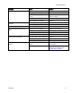
Parts Parts/Kits Quick Reference Use this table as a quick reference for parts/kits. Go to the pages indicated in the table for a full description of kit contents. Ref. Part/Kit Description Qty. Ref.
Parts Center Section Sample Configuration Number Pump Model Center Section and Air Valve Fluid Covers and Manifolds Seats Balls Diaphragms Seat and Manifold Seal 2200P P01A P1 PP PT FK PT Ref Description Qty Ref Description Qty 101 1 108* SHAFT, center 1 102 HOUSING, center, not sold separately VALVE, air, see page 24 1 109* CARTRIDGE, pilot receiver 2 103 SCREW, hi-lo stud 4 110* O-RING, Buna-N 2 104* NUT, hex, flange, serrated 4 111* VALVE, pilot, assembly 2 105*
Parts Sample Configuration Number Pump Model Center Section and Air Valve Fluid Covers and Manifolds Seats Balls Diaphragms Seat and Manifold Seal 2200P P01A P1 PP PT FK PT Center Section Rebuild Kits (*) Center Shaft Kits (*) P01A with 2–Piece diaphragms (PT) or standard diaphragms (SP, FK) 24V226 P01A with 2–Piece diaphragms (PT) or standard diaphragms (SP, FK) 24V228 PO1G with overmolded diaphragms (PO) 24V227 PO1G with overmolded diaphragms (PO) 24V229 Kits include: Kits include
Parts Air Valve Sample Configuration Number Pump Model Center Section and Air Valve Fluid Covers and Manifolds Seats Balls Diaphragms Seat and Manifold Seal 2200P P01A P1 PP PT FK PT Ref Description Qty Ref Description Qty 201 1 209✦✝ SCREW, #4, thread forming 2 202✦ HOUSING, not sold separately PISTON 210‡ RETAINING RING 2 205✦ PLATE, air valve 1 212✦ BASE, cup 1 206✦✝‡ O-RING 2 213✦ CUP 1 207‡ CAP, end 2 214✦ O-RING, cup 1 208✦✝ U-CUP 2 ✦ Parts included i
Parts Sample Configuration Number Pump Model Center Section and Air Valve Fluid Covers and Manifolds Seats Balls Diaphragms Seat and Manifold Seal 2200P P01A P1 PP PT FK PT Air Valve Replacement Kit ✝ Air Valve Seals Kit All models All models 24K859 Kit includes: Kits include: • 2 end cap o-rings (206) • 1 air valve assembly (102) • 2 piston u-cups (208) • 1 air valve gasket (105) • 2 screws, M3, shorter (not used) • 4 hex nuts (104) • 2 screws, #4, longer (209) ‡ Air Valve End Ca
Parts Fluid Covers and Manifolds Sample Configuration Number Pump Model Center Section and Air Valve Fluid Covers and Manifolds Seats Balls Diaphragms Seat and Manifold Seal 2200P P01A P1 PP PT FK PT Fluid Cover Kits Polypropylene P1, P2 24V234 End Inlet Manifold Kits PVDF F2 Polypropylene 24V240 P2 PVDF 24V239 F2 24V415 Kits include 1 manifold (4) Kits include 1 fluid cover (2) Fluid Cover Fastener Kits All Models Center Manifold Kits (Polypropylene Only) P1 Outlet (3) Inlet (4) 2
Parts Seats and Check Balls Sample Configuration Number Pump Model Center Section and Air Valve Fluid Covers and Manifolds Seats Balls Diaphragms Seat and Manifold Seal 2200P P01A P1 PP PT FK PT Seat Kits Ball Kits PP 24V248 FK 24V253 SS 24V250 PT 24V251 SP 24V249 SP 24V252 PV 24V247 Kits include: Kits include: • 4 balls (8), material indicated in table. • 4 seats (7), material indicated in table. NOTE: O-rings are sold separately. See Manifold Seals, page 30..
Parts Diaphragms Sample Configuration Number Pump Model Center Section and Air Valve Fluid Covers and Manifolds Seats Balls Diaphragms Seat and Manifold Seal 2200P P01A P1 PP PT FK PT Standard Diaphragm Kits SP 24V242 FK 24V243 Kits include: Overmolded Diaphragm Kit PO 24V241 Kits include: • 2 diaphragms (12), material indicated in table • 2 overmolded diaphragms (12), material indicated in table.
Parts Sample Configuration Number Pump Model Center Section and Air Valve Fluid Covers and Manifolds Seats Balls Diaphragms Seat and Manifold Seal 2200P P01A P1 PP PT FK PT Two-Piece Diaphragm Kit Fluid Plate Kits PT P1, P2 24V245 F2 24V246 24V244 Kits include: • 2 diaphragms (12), PTFE Kits include: • 2 backup diaphragms (13), Santoprene • 1 fluid side diaphragm plate (10), includes shaft bolt • 1 diaphragm install tool (302) • 1 packet anaerobic adhesive • 1 packet anaerobic adh
Parts Manifold Seals Sample Configuration Number Pump Model Center Section and Air Valve Fluid Covers and Manifolds Seats Balls Diaphragms Seat and Manifold Seal 2200P P01A P1 PP PT FK PT Standard Manifold O-Ring Kits Kits include: All Models • 8 o-rings (9), material shown in tables PTFE 24V236 Optional Manifold O-Ring Kits PTFE-Encapsulated FKM 24V978 FX75 24W463 30 3A2714B
Accessories Accessories Muffler 111897 Legacy or remote exhaust muffler option. NOTE: See DataTrak Manual 313840 for: • Pulse Count Conversion Kits 24B794 and 24B795 • DataTrak Conversion Kits 24K861 and 24K862 • All other data monitoring parts, including reed switches and solenoids. Replacement Air Valve Kit 24V232, Polypropylene, DataTrak Compatible Kit includes nuts, valve, and gasket.
Technical Data Technical Data Husky 2200 Diaphragm Pump Maximum fluid working pressure Air pressure operating range US Metric 125 psi 0.86 MPa, 8.6 bar 20 to 125 psi 0.14 to 0.86 MPa, 1.4 to 8.6 bar Air inlet size 3/4 in. npt(f) Air exhaust size 1 in. npt (f) 2 in 50 mm Wet: 31 ft Dry: 16 ft Wet: 9.4 m Dry: 4.9 m 1/4 in. 6.3 mm 32° F 0° C Standard diaphragms 70 scfm at 70 psi; 100 gpm Overmolded diaphragms 75 scfm at 70 psi, 100 gpm 2.0 m3/min at 0.48 MPa, 4.8 bar, 379 lpm 2.
Technical Data Maximum pump speed Standard diaphragms 125 cycles per minute Overmolded diaphragms 155 cycles per minute Weight Polypropylene 80 lb 36.3 kg PVDF 106 lb 48.
Graco Standard Husky Pump Warranty Graco warrants all equipment referenced in this document which is manufactured by Graco and bearing its name to be free from defects in material and workmanship on the date of sale to the original purchaser for use. With the exception of any special, extended, or limited warranty published by Graco, Graco will, for a period of five years from the date of sale, repair or replace any part of the equipment determined by Graco to be defective.