Instructions/Parts SaniForce® 2:1 Sanitary Piston 3A2977D Pumps EN For use in sanitary applications to transfer low- to medium-viscosity fluids. Use with non-flammable liquids only. For professional use only. Important Safety Instructions Read all warnings and instructions in this manual. Save these instructions. Maximum Fluid Working Pressure: 250 psi (1.7 MPa, 17.0 bar) PROVEN QUALITY. LEADING TECHNOLOGY.
Contents Models............................................................... 3 Warnings ........................................................... 5 Installation.......................................................... Grounding ................................................... Mounting ..................................................... Setup .......................................................... 7 7 7 7 Operation ...........................................................
Models Models See ID tag on side of air motor (located under the motor cover) for model number. Maximum Air Inlet Pressure: 100 psi (0.7 MPa, 6.9 bar) Maximum Fluid Working Pressure: 250 psi (1.7 MPa, 17.0 bar) Pump Model Pump Type Pump Description Packings 24N300 Double Ball Tall Drum Length (42 in., 107 cm Drum) U-Cup, UHMWPE 24N344 Double Ball Tall Drum Length (42 in., 107 cm Drum) U-Cup, PTFE 24R046 Double Ball Standard Drum Length (34 in.
Material Certification SaniForce Product Family Issue Date: April 24, 2013 All fluid contact materials in the SaniForce product family are FDA-Compliant and meet the United States Code of Federal Regulations (CFR) Title 21, Section 177 or are of a corrosion resistant grade Stainless Steel.
Warnings Warnings The following warnings are for the setup, use, grounding, maintenance and repair of this equipment. The exclamation point symbol alerts you to a general warning and the hazard symbol refers to procedure-specific risks. When these symbols appear in the body of this manual or on labels refer back to these Warnings. Product-specific hazard symbols and warnings not covered in this section may appear throughout the body of this manual where applicable.
Warnings WARNING EQUIPMENT MISUSE HAZARD Misuse can cause death or serious injury. • Do not operate the unit when fatigued or under the influence of drugs or alcohol. • Do not exceed the maximum working pressure or temperature rating of the lowest rated system component. See Technical Data in all equipment manuals. • Use fluids and solvents that are compatible with equipment wetted parts. See Technical Data in all equipment manuals. Read fluid and solvent manufacturer’s warnings.
Installation Installation Grounding during operation. Do not use air or fluid lines to support the pump. Setup The equipment must be grounded to reduce the risk of static sparking. Static sparking can cause fumes to ignite or explode. Grounding provides an escape wire for the electrical current. Pump: Connect a ground wire (Graco PN 238909) to the ground screw on the air motor base. Connect the other end of the ground wire to a true earth ground.
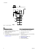
Installation Figure 1 Typical Installation Key Pump Components (Included) System Components/Accessories (sold separately) A Bung-mounted sanitary pump F Air line filter/regulator (Graco PN 234398) B G Bleed-type master air valve (required) C Air exhaust muffler (may be mounted on pump or remotely, using exhaust hose, ref. M) 3/8 npt exhaust air outlet H Air line drain pipe and valve D 3/8 npt air inlet J Main air line E 1 in.
Operation Operation NOTICE Do not expose the air motor to temperatures higher than 120°F (49°C) or the immersed fluid pump to temperatures higher than 250°F (121°C). Excessive temperatures may damage the pump packings and seals. Flush Before First Use The sanitary pump was assembled using sanitary lubricant on moving parts and was tested in water. Flush the pump thoroughly with an appropriate cleaning solution or disassemble and sanitize the parts before using the pump. See Flushing Procedure, page 10.
Maintenance Maintenance Flushing Procedure Note: • Flush before fluid can dry in the equipment, at the end of the day, before storing, and before repairing equipment. • Flush at the lowest pressure possible. Check connectors for leaks and tighten as necessary. • Flush with an appropriate cleaning solution. 1. Follow Pressure Relief Procedure, page 9 . 2. Remove the pump from the fluid container. Place it in an empty drum. Operate it to pump out as much fluid as possible. 3.
Troubleshooting Troubleshooting 1. Follow Pressure Relief Procedure, page 9 . 2. Check all possible remedies in the Troubleshooting Chart before disassembling the pump. Problem Cause Solution Pump cycles, but no fluid comes out. Fluid supply is empty. Replace fluid supply. Pump cycles, but fluid flow is too slow. Air supply flow or pressure is inadequate. Improve air supply flow, increase pressure, or increase air line size. Air valves are closed or clogged. Open air line. Use dry air.
Repair Repair Disconnect the Air Motor 1. Follow the Pressure Relief Procedure, page 8. 2. See Figure 11, page 17. 3. Release the top clamp (5). 4. Tilt the air motor and unhook the shaft from the displacement rod. Lift the air motor up and off the rest of the pump. 5. Release the bottom clamp (5). Remove connector (3) and gasket (2). 6. Remove the bung adapter clamp. 7. Pull the displacement pump straight up and out of the container. Air Motor Disassembly 1.
Repair 5. Air Valve Disassembly: Follow these steps to disassemble the air valve for cleaning or parts replacement. 6. Air Valve Replacement: Follow these steps to replace the entire air valve, without disassembly. a. Remove three screws (114), then remove the valve cap (108). Remove gasket (107) and spacers (111). a. Purchase Kit 262035 to replace entire valve assembly. b. Clamp piston in a vice. Hold the piston cap with a spanner wrench and unscrew the air valve (105).
Repair 7. Slide the air piston (124) out of the top of the air motor base (118). Remove o-ring (120) and gasket (102) from inside the air motor base. Remove o-ring (123) from groove on outside of base. Inspect all parts, including the spring (122) in the air motor base. NOTE: Do not remove the spring (122) and retainer (121) if you do not have to. NOTE: If the white bushing (119) needs to be replaced, use an arbor press to remove.
Repair 7. Reassemble the air valve (if needed): Lubricate and install a new o-ring (106) on the air valve (105). Lubricate and install the three o-rings (112), then install the spacers (111). Install gasket (107) and valve cap (108). Apply blue Loctite or equivalent on the screw threads. Torque the screws to 20 to 30 in-lb (2.3 to 3.4 N•m). Skip Step 8 and go to Step 9. 8. Install assembled air valve from kit: Lubricate and install new o-rings (106 and 115).
Repair Disassemble the Pump If not yet done, follow steps in Disconnect the Air Motor, page 12. Note: Be careful not to scratch the displacement rod. Carry to the bench for service. all the way. Then, remove the cartridge (215). Remove o-rings (216, 220). Use a screwdriver to push the u-cup (217) out of the center of the cartridge. Be careful not to damage the lips. 1. Use a pick to move the o-rings (208) to the center of the inlet seat pin (214).
Repair 4. Push the displacement rod (202) all the way out the bottom of the cylinder. Reassemble After Cleaning Note: Any damaged parts must be replaced. Note: Lubricate the o-rings, throat packings, and piston seals with appropriate waterproof sanitary lubricant. 1. Lubricate and install u-cup (204) and bearing (205) on the piston seat (203). U-cup lip must face up. Lubricate and install o-rings (218) on the seat assembly. Install the ball (207), then the seat assembly in the outlet housing. 2.
Repair 8. Lubricate and install o-ring (211) on inlet seat (210), then install seat (210) in inlet housing (209). Use the pin to align the holes. 9. Lubricate and install o-ring (216) on inlet housing (209), then install the ball (213) and pin (212). 10. Slide the assembled housing into the bottom of the cylinder. 11. Push the pin (214) through the holes on one side. Lubricate and install o-rings (208) from the inside, putting one in each groove on the pin. Then slide the pin into the second side.
Notes Notes 3A2977D 19
Parts Parts Apply sanitary grease before assembling cover.
Parts Complete Pump Models 24N300, 24N344, 24R046, and 24R047 Ref. Part Description Qty. Ref. 1 10 2 24R180* MOTOR, SaniForce; 2:1, see Air Motor Parts.* 166117 GASKET, sanitary fitting 2 14 3 16U981 CONNECTOR 1 5 620223 CLAMP, 2.5 in. Tri-clamp DISPLACEMENT PUMP; see Displacement Pump Parts. Used on Pump Model 24N300 Used on Pump Model 24N344 Used on Pump Model 24R046 Used on Pump Model 24R047 MUFFLER 1 6 24R190 24R189 24R192 24R191 7 112933 3A2977D Part Description Qty.
Parts Air Motor 24R180 Torque to 50 to 60 in-lb (5.6 to 6.8 N•m). Apply sanitary lubricant. Apply medium-strength thread locker. Torque to 15 to 20 ft-lb (20.3 to 27.1 N•m). Torque to 20 to 30 in-lb (2.3 to 3.4 N•m). Apply pipe sealant.
Parts Air Motor 24R180 Parts Description O-RING, buna-N 2 121 16P926 RETAINER, o-ring 1 CAP, air cylinder 1 122 15J551 SPRING, compression 1 SPRING, tapered 1 123 U22665 O-RING 1 HEAD, air piston 1 124 24R176 1 O-RING, buna-N 1 125 24R177 126◗ 111819 127 116343 PISTON, air, assembly; includes Bushing (ref. 119) and o-ring (ref. 120) FITTING, inlet/outlet, stainless steel, 1/2–18 to 3/8–18 npt; includes o-ring (ref. 126) O-RING; included with ref.
Parts Displacement Pump Models 24R189, 24R190, 24R191, and 24R192 Apply sanitary lubricant.
Parts Displacement Pump Parts Ref. Part 201 24R193 24R194 202 24R183 24R184 203 16P149 204✷ 16P254 16P044 205✷ 16P150 206 16P147 207 104585 208✷ ——— 209 210 3A2977D Description CYLINDER, pump 1 Models 24R190 and 24R189 Models 24R192 and 24R191 ROD, displacement 1 Models 24R190 and 24R189 Models 24R192 and 24R191 SEAT, outlet; sold with ball (ref.
Kits and Accessories Kits and Accessories Replacement Parts Kits Kit Includes ✦ 24R175, Air Motor Seals Gasket (102), o-rings (106, 115, 120), and upper gasket (107) ✝ 262035, Air Valve Kit Piston head (105), upper gasket (107), valve cap (108), spacer (111), piston disk (113), screws (114), and o-rings (106, 112, 115) ✷ 24R187, UHMWPE Pump Seals Kit OR 24R188, PTFE Pump Seals Kit Piston check bearing (205), u-cup cartridge (215), u-cups (214, 217), and o-rings (208, 211, 216, 218, 220) ✓ 24R185, U
Dimensions Dimensions Model 24N300 and 24N344 Model 24R046 and 24R047 in. cm in. cm A 61.9 157.2 54.9 139.4 B 53.7 136.4 46.7 118.6 C 44.5 113.0 37.5 95.2 D (fluid inlet OD) 1.972 5.0 1.972 5.0 E (air inlet) 3/8 npt (f) 9.5 npt (f) 3/8 npt (f) 9.5 npt (f) F (air exhaust) 3/8 npt (m) 9.5 npt (m) 3/8 npt (m) 9.5 npt (m) 1 2.5 1 2.
Performance Chart Performance Chart Test Conditions: Pump tested in water. Cycles per Minute 0 20 40 60 80 100 14 (0.39) 300 (2.1, 21) 12 (0.33) A 250 (1.7, 17) A 200 (1.4, 13) Fluid Outlet Pressure psi (MPa, bar) 10 (0.28) B 8 (0.23) B 150 (1.0, 10) 6 (0.17) C 100 (0.7, 7) Air Flow scfm (m3/min) C 4 (0.11) 50 (0.3, 3) 2 (0.06) 0 0 0 0.5 (1.9) 1.0 (3.8) 1.5 (5.7) 2.0 (7.6) 2.5 (9.5) Fluid Flow — gpm (lpm) KEY: A 100 psi (0.7 MPa, 7 bar) Inlet Air Pressure B 70 psi (0.
Technical Data Technical Data Metric U.S. Maximum Fluid Working Pressure 250 psi 17 bar, 1.7 MPa Air Inlet Pressure Range 30 to100 psi 2.1 to 6.9 bar, 0.2 to 0.7 MPa Maximum Recommended Pump Speed 100 cycles/min, 2.5 gpm delivery 100 cycles/min, 9.5 liters/min delivery Pump Cycles per Gallon (3.8 Liters) 40 Ratio 2.
Graco Standard Warranty Graco warrants all equipment referenced in this document which is manufactured by Graco and bearing its name to be free from defects in material and workmanship on the date of sale to the original purchaser for use. With the exception of any special, extended, or limited warranty published by Graco, Graco will, for a period of twelve months from the date of sale, repair or replace any part of the equipment determined by Graco to be defective.