
User's Manual


Installation
Installation
Grounding
The equipment must be grounded to reduce the
risk of static sparking. Static sparking can cause
fumes to ignite or explode. Grounding provides an
escape wire for the electrical current.
Pump: Connect a ground wire (Graco PN 238909) to
the ground screw on the air motor base. Connect the
other end of the ground wire to a true earth ground.
Air and fluid hoses: Use only electrically conductive
hoses with a maximum of 500 ft. (150 m) combined
hose length to ensure grounding continuity. Check
electrical resistance of hoses. If total resistance
to ground exceeds 25 megohms, replace hose
immediately.
Air compressors: Follow manufacturer’s
recommendations.
Dispense valve: Ground through connection to a
properly grounded fluid hose and pump.
Material supply container: Follow local code.
Container(s) that receive material: Follow local code.
Solvent pails used when flushing: Follow local
code. Use only conductive metal pails, placed on
a grounded surface. Do not place the pail on a
nonconductive surface, such as paper or cardboard,
which interrupts grounding continuity.
To maintain grounding continuity when flushing or
relieving pressure: Hold metal part of the dispense
valve firmly to the side of a grounded metal pail, then
trigger the valve.
Mounting
Mount the pump to fully support the weight of the
pump and accessories, as well as the stress caused
during operation. Do not use air or fluid lines to
support the pump.
Setup
To avoid contaminating the fluid, pipe the exhaust
air to vent outside of the fluid product area, away
from people, animals, or food handling areas.
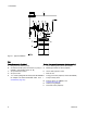
Note
Reference numbers and letters in
parentheses in the text refer to the callouts in
the figures and the parts drawings.
Accessories are available from Graco. Make certain
all accessories are sized and pressure rated to meet
your system requirements.
Figure 1 is only a guide for selecting and installing
system components and accessories. Contact your
Graco distributor for assistance in designing a system
to suit your particular needs.
Install a fluid drain valve (P) close to the fluid outlet to
relieve fluid pressure in the hose.
Install a bleed-type master air valve (G) close to the
pump air inlet (D), to relieve air trapped between it
and the air motor.
Install an air filter/regulator (F) in the pump air
line,
upstream from the bleed valve,
to control
air inlet pressure and to remove harmful dirt and
contaminants from your compressed air supply.
Install a pump runaway valve (L) in the pump air line
to shut off air to the air motor automatically if the
pump starts to run too fast.
Install another bleed-type master air valve (G)
upstream from all air line accessories and use it to
isolate the accessories during cleaning and repair.
3A2977D
7