Instructions Parts 28:1/33:1 RATIO, WALL MOUNT Bulldogr Pumps 307932R For ambient temperature spray applications. Part No. 245187, 33:1, Series B 3300 psi (22.8 MPa, 228 bar) Maximum Fluid Working Pressure 100 psi (700 kPa, 7 bar) Maximum Air Input Pressure Part No. 253697, 28:1, Series A 2800 psi (19.3 MPa, 193 bar) Maximum Fluid Working Pressure 100 psi (700 kPa, 7 bar) Maximum Air Input Pressure Part No. 245185, Series B (240 Volt Heater) Part No.
Table of Contents Warnings . . . . . . . . . . . . . . . . . . . . . . . . . . . . . . . . . . . . . . 2 Installation . . . . . . . . . . . . . . . . . . . . . . . . . . . . . . . . . . . . . 5 Operation/Maintenance . . . . . . . . . . . . . . . . . . . . . . . . 14 Parts . . . . . . . . . . . . . . . . . . . . . . . . . . . . . . . . . . . . . . . . 17 Mounting Hole Layout . . . . . . . . . . . . . . . . . . . . . . . . . . 20 Technical Data . . . . . . . . . . . . . . . . . . . . . . . . . . . . . . . .
WARNING SKIN INJECTION HAZARD Spray from the gun, leaks or ruptured components can inject fluid into your body and cause extremely serious injury, including the need for amputation. Fluid splashed in the eyes or on the skin can also cause serious injury. Fluid injected into the skin might look like just a cut, but it is a serious injury. Get immediate surgical treatment. Do not point the gun at anyone or at any part of the body. Do not put your hand or fingers over the spray tip.
WARNING FIRE AND EXPLOSION HAZARD Improper grounding, poor ventilation, open flames or sparks can cause a hazardous condition and result in a fire or explosion and serious injury. Ground the equipment and the object being sprayed. Refer to Grounding on page 5. If there is any static sparking or you feel an electric shock while using this equipment, stop spraying immediately. Do not use the equipment until you identify and correct the problem.
Installation General Information W X NOTE: Reference numbers and letters in parentheses in the text refer to the callouts in the figures and the parts drawing. NOTE: Always use Genuine Graco Parts and Accessories, available from your Graco distributor. Refer to the Product Data Sheet for your pump, Form No. 305791. If you supply your own accessories, be sure they are adequately sized and pressure rated for your system. NOTE: Fig.
Installation Supplied Components System Accessories Refer to Fig. 2 for a typical installation of an airless system. Air and Fluid Hoses WARNING A red-handled bleed-type master air valve (14) and a fluid drain valve (7) are supplied in your system. These accessories help reduce the risk of serious injury, including fluid injection and splashing of fluid in the eyes or on the skin, and injury from moving parts if you are adjusting or repairing the pump.
Installation KEY SUPPLIED COMPONENTS ACCESSORIES YOU MUST SUPPLY 1 2 4 7 8 14 15 24 25 45 A B C D E F G H J Pump Pump Wall Bracket Fluid Filter Fluid Drain Valve (required) Pump Air Regulator Red Handled Bleed-Type Master Air Valve (required, for pump) Air Manifold Suction Hose Suction Tube Ground Wire (required; see page 5 for installation instructions) B Electrically Conductive Air Hose Air Line Filter Bleed-Type Master Air Valve (for accessories) Air Line Drain Valve Air Line Lubricator Pump Runawa
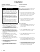
Installation Models 245187 and 253697 (for Ambient Temperature Spray Applications) NOTE: Refer to page 10 to convert Pump Model 245187 or 253697 to a heated system. 1. Mount the pump wall bracket (2) 5 ft (1.5 m) above the floor. Be sure the wall is strong enough to support the weight of the pump and accessories, fluid, hoses, and stress caused during pump operation. Refer to Mounting Hole Layout on page 20. 2 2. Connect the air and fluid hoses and the spray gun as explained on page 6.
Installation Models 245185 and 245186 (for Heated Temperature Spray Applications) 4. Use M8 or 5/16 in. bolts of the appropriate length and lockwashers (not supplied) to fasten the heater brackets to the wall. 1. Be sure the wall is strong enough to support the weight of the pump and accessories, heaters, hoses, fluid, and stress caused during operation. 5. Bring the hose (31a) from the inlet elbow (32a) of the lower heater (44a) and connect it securely to the swivel (50) coming from the pump outlet.
Installation Converting to a Heated System To convert Model 245187 or 253697 to a heated circulating system, order the following parts. The heaters are available in three voltages. Specify which voltage you desire. Two Viscon HP Fluid Heaters – Model 245848 (120 V, single-phase, 19.2 amp) – Model 245863 (240 V, single-phase, 16.7 amp) – Model 245864 (480 V, single-phase, 8.
Installation 5. Screw the 3/4 npt street elbow (28*) into the pump’s fluid outlet. Assemble the nipple (27*), check valve (29*), coupling (30*), and swivel (50*) as shown in Fig. 6. The arrow on the check valve must point down, toward the coupling. 6. Screw an elbow (32*) onto the lower heater’s inlet. Screw the coupler (63) onto the elbow. Attach the heater hose (31*) to the coupler. Connect the other end of the hose to the swivel (50*) coming from the pump outlet. 7.
Installation Installing Circulating Kit 222312 WARNING Before installing the heaters, dual heater mounting kit and circulating kit, follow the Pressure Relief Procedure on page 14. Disconnect all hoses from the pump. NOTE: Reference numbers marked with a symbol (for example, 37 ) are included in kit 222312. Apply pipe sealant (36 ) to all male threads except at swivel connections. 1. Remove the suction tube (25), fittings (52 and 53), hose (24), and adapter (12). See Fig. 5. Keep these parts for use later.
Installation 1 Specify desired heater voltage (see page 10). 4 Connect to the main fluid supply line to the guns. 2 Part of the heater (44). 5 Connect to the main fluid return line. 3 Arrow must point down. 5 34* 44 4 64* 1 1 35* 26* 51 4 44 1 20 6 33* 62 33* 45 31 62 7 2 34* 64* A A 32* *31 31* (Ref) C C 21 22 2 32* 28* B 27* 47 22 29* 3 31* (Ref) 37 11 5 38 54 39 30* 48 64* 12 31* 24 B 41 39 40 49 55 42 52 53 25 Fig.
Operation/Maintenance Pressure Relief Procedure Packing Nut/Wet-Cup WARNING SKIN INJECTION HAZARD The system pressure must be manually relieved to prevent the system from starting or spraying accidentally. Fluid under high pressure can be injected through the skin and cause serious injury.
Operation/Maintenance Starting and Adjusting the Pump 1. Be sure the air regulator and bleed-type master air valve are closed. NOTE: Do not install the spray tip yet! 2. Open the bleed-type master air valve. 3. Hold a metal part of the spray gun firmly to the side of a grounded metal pail and trigger the gun. 4. Slowly open the air regulator until the pump starts. 5. Allow the pump to cycle slowly until all the air is pushed out of the fluid lines. 6.
Operation/Maintenance Shutdown and Care of the Pump WARNING To reduce the risk of serious injury whenever you are instructed to relieve pressure, always follow the Pressure Relief Procedure on page 14. For overnight shutdown, stop the pump at the bottom of its stroke to prevent fluid from drying on the exposed displacement rod and damaging the throat packings. Relieve the pressure. Always flush the pump before the fluid dries on the displacement rod. See Flushing below.
Parts Model 245187, 33:1, Series B Model 253697, 28:1, Series A Ref No. Part No.
Parts Model 245185, Series A (240 Volt Heater) Model 245186, Series A (480 Volt Heater) Ref No. Part No.
Parts Model 245185, Series A (240 Volt Heater) Model 245186, Series A (480 Volt Heater) 5 34* 1 Specify desired heater voltage (see page 10). 5 Connect to the main fluid supply line to the guns. 2 Part of the heater (44). 6 Connect to the main fluid return line. 3 See Check Valve Detail. 4 See Air Regulator Detail.
Mounting Hole Layout M8 or 5/16 in. diameter holes for heater wall brackets (or use brackets as templates to mark wall). 12.375 in. (314 mm) 6 in. (152 mm) 15 in. (381 mm) 5 in. (127 mm) 7.375 in. (187 mm) 8.5 in. (216 mm) 6 in. (152 mm) 7/16 in. diameter holes for pump wall bracket (mount 5 ft [1.5 m] above floor; refer to 306783 for instructions).
Technical Data Category Data Maximum fluid working pressure Model 245187: 3300 psi (228 bar, 22.8 MPa) Models 245185, 245186: 3000 psi (207 bar, 20.7 MPa) Model 253697: 2800 psi (193 bar, 19.
Graco Standard Warranty Graco warrants all equipment manufactured by Graco and bearing its name to be free from defects in material and workmanship on the date of sale to the original purchaser for use. With the exception of any special, extended, or limited warranty published by Graco, Graco will, for a period of twelve months from the date of sale, repair or replace any part of the equipment determined by Graco to be defective.