INSTRUCTIONS-PARTS LIST This manual contains important Model AA2000 High Efficiency Low Pressure” Air-Assisted Part Number 222-615, System Airless Spray Gun Series C 950 psi (66 bar) Maximum Working Fluid Pressure 100 psi (7 bar) Maximum Working Air Pressure * 10 psi (0.7 bar) Maximum Operating Air Pressure** * The Maximum Workina Air Pressurq indicates the maximum air pressure the gun was designed to operate safely under.
Table of Contents SafetyWarnings ............................... 3 Installation Ventilate the Spray Booth ..................... Required Accessories ........................ Connect the Air Line ......................... Connect the Fluid Line ....................... Grounding .................................. 6 6 7 7 7 Operation How Air-Assisted Airless Spray Gun Operates ... 7 Select A Spray Tip ........................... 8 Install a Spray Tip ............................
WARNINGS High Pressure Spray Can Cause Serious Injury. For Professional Use Only. Observe All Warnings. Read and understand all instruction manuals before operating equipment. FLUID INJECTION HAZARD General Safety This equipment generates very high fluid pressure. Spray from the gun, leaks or ruptured components can inject fluid through your skin and into your body and cause extremely serious injury, including the need for amputation.
Static electricity is created by the flow of fluid through the pump and hose. If every part of the equipment is not properly grounded, sparking may occur, and the system may become hazardous. Sparks can ignite fumes from solvents and the fluid being sprayed, dust particles and other flammable substances, whether you are pumping indoors or outdoors, and cause a fire or explosion, serious injury, and property damage. Sparks may also occur when plugging in or unplugging a power supply cord.
General Safety Any misuse of the equipment or accessories, such as overpressurizing, modifying parts, using incompatible chemicals and fluids, or using worn or damaged parts, can cause them to rupture and result in serious injury, including fluid injection and splashing fluid in the eyes or on the skin, or in fire, explosion or property damage.
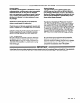
Installation KEY A B C D E F Gun Air Inlet Gun Fluid Inlet Bleed-Type Master Air Valve Main Air Supply Line Pump Air Regulator Gun Air Regulator, p/n 110-776, 10 psi (0.7 bar)Maximum Outlet Pressure G Pump Ground Wire H Air Line Filter J Fluid Drain Valve K Gun Air Hose L Gun Fluid Hose M Fluid Regulator Kit N Fluid Filter P Air Pressure Relief Valve Fig. 1 shown in Fig.1 is only a guide The typical installation for selecting and installing air-assisted airless spray systems.
Installation Connect the Air Line Install fluid drain valve(s) (J) to help relieve fluid pressure. Install an air line filter (H) to ensure a clean, dry air supply to the gun. Dirt and moisture in the line can ruin the appearance of your finished piece. NOTE: The gun fluid connector (6) has a l/4-18 npsm (Rl/4- 19) compound male thread that is compatible with NPSM and BSP female connectors. Install Air Pressure Regulator 1lo-776 (F) to control the air pressure to the gun and limit it to 10 psi (0.
Operation Select a Spray Tip Horizontal Spray Pattern Vertical Spray Pattern Use the Spray Tip Selection charts on page 18, as a guide for selecting an appropriate spray tip for your application. The fluid output and pattern width depend on the size of the spray tip, the fluid viscosity, and the fluid pressure. NOTE: When spraying very low viscosity fluids, use the optional fluid needle 220-413 (see page 15). The standard needle may not provide positive shut off for such fluids.
Operation Adjust the Spray Pattern & Apply the Fluid (Continued’ 1. Increase the fluid pressure just to the point where a further increase in fluid pressure does not significantly improve fluid atomization. Do not exceed 950 psi (66 bar) fluid pressure to the gun. 4. When applying the fluid, keep the gun a consistant distance, 8 to 10 inches (200 to 250 mm), from the surface of the object being sprayed. Always hold the gun at a right angle from the surface.
Operation Flush the Gun Daily WARNING Dressure Relief Procedure Toreduce the risk of serious injury, including fluid njection, splashing in the eyes or on skin, or injury ‘ram moving parts, always follow this procedure Nhenever the pump is shut off, when checking or servicing any part of the system, when installing or :hanging spray tips and whenever you stop spraying. 1. Engage the spray gun safety latch. 2. Shut off the power to the pump. 3. Close the bleed-type master air valve (required in system). 4.
Troubleshooting I WARNING To reduce the risk of serious injury, including fluid injection, splashing fluid or solvent in the eyes or on the skin, or injury from moving parts, always follow the Pressure Relief Procedure Warning on page 10 whenever you shut off the pump, when checking or servicing any part of the spray system, when installing, cleaning or changing spray tips, and whenever you stop spraying. NOTE: Check all possible remedies in the Troubleshooting Charts before disassembling the gun.
Service WARNING To reduce the risk of serious injury, including fluid injection, and splashing in the eyes or on the skin, or injury from moving parts or electric shock, always follow the Pressure Relief Procedure Warning on page 10 before servicing any part of the gun or system. NOTE: Follow the Service Notes in Fig. 7 when reassembling the gun. Also refer to the parts drawing on page 14 for parts not shown in Fig. 7. Air Valve Service 1. Remove the trigger (3) and valve cap (11). See Fig. 7.
Service 27 SERVICE NOTES: A Gasket (33) must be replaced if fluid connector (67 or l-see page 14) is removed or replaced. Fluid leakage into air chambers may result if new gasket is not installed.
18 26 28 \ A3 67 A 32 SERVICE NOTES (See Fig. 7 for additional Informatlon): For Direct Hose Connection (Paris shipped unassembled) 14 307-947 A Gasket (33) must be replaced if fluid connector (67 or 1) is removed or replaced. Fluid leakage into air chambers may result if new gasket is not installed.
Use Only Genuine Grace Parts and Accessories. Ref. No. Part No. 1 178-415 2 3 5*A 7 10* 11 18 19 20 21* 24*& 25 26* 27 28 Qty- Description CONNECTOR, fluid (not assembled) 106-917 ADAPTER, air 178-454 TRIGGER, gun 217-488 NEEDLE, fluid 217-489 VALVE, pattern adjustment; Includes items 62 & 63 106-903 SPRING, compression, air valve 178-408 CAF1valve, air 203-953 CAPSCREW, hex hd, 1O-24 x 0.
Accessories Use Only Genuine Grace Parts and Accessories Fluid Filters 3000 psi (207 bar) Maximum Working Pressure 214-570 with carbon steel bowl and support. 218-029 with aluminum bowl and support.
Accessories Use Only Genuine Grace Parts and Accessories Air Pressure Verification Kit 224-250 For use in checking air cap pressure at various gun inlet pressures. Do not use the air cap for spraying. Assemble the kit as shown in the drawing below. Install the air cap on the gun. Turn on the air to the gun, then actuate the gun and read the resulting air cap pressure.
Spray Tip Selection STANDARD SPRAY TIPS Orlflce Size Inches) 0.007 0.009 0.011 0.013 Inches Fan Wldth at 12” (300 mm) 2-4(50-100) 4-6(1W-150) S-8(150-200) 8-10(2W-250) 4-6(1W-150) S-8(150-200) 6-10(200-250) *Light to Medlum Vlscoslty A oz/mln (Ilters/mln) *Heavy vlscoslty fl oz/mln (Iiterslmln) (04; Orlflce Size Inches) Part No. 182-107 182-207 182-307 182-407 4-6(1W-150) 6-8(150-200) S-10(200-250) lo-12(250-300) 12-14(300-350) 10.0 (0.
Technical Data Dimensions Maximum Working Fluid Pressure . . . 950 psi (66 bar) *Maximum Working Air Pressure . . . . . . . 100 psi (7 bar) **Maximum Operating Air Pressure . . . . . 10 psi (0.7 bar) Weight (less filter) . . . . . . . . . . . . . . . . . . 1.2 lb (0.55 Kg) Wetted Parts . . . . . . . Stainless Steel, Carbide, Ultra Weight Molecular High Polyethylene, PTFE Delrin@ PTFE and De/h@ are registered trademarks of the DuPont co.
The Grace Warranty and Disclaimers WARRANTY Waco warrants all equipment manufactured by it and bearing its name to be free from defects in material and workmanship on the date of sale by an authorized Grace distributor to the original purchaser for use. As purchaser’s sole remedy for breach of this warranty, Grace will, for a period of twelve months from the date of sale, repair or replace any part of the equipment proven defective.