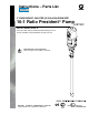
Instructions – Parts List Parts 2” BUNG MOUNT, 200 LITER (55 GALLON) DRUM SIZE 10:1 Ratio Presidentr Pump 308738C Part No. 239326, Series A 62 bar (6.2 MPa, 900 psi) Maximum Fluid Working Pressure 6.2 bar (0.62 MPa, 90 psi) Maximum Air Input Pressure Read warnings and instructions. Refer to page 2 for the Table of Contents. GRACO INC.ąP.O. BOX 1441ąMINNEAPOLIS, MNą55440-1441 Copyright 1998, Graco Inc. is registered to I.S.
Table of Contents Warnings . . . . . . . . . . . . . . . . . . . . . . . . . . . . . . . . . . . . . . 2 Installation . . . . . . . . . . . . . . . . . . . . . . . . . . . . . . . . . . . . . 5 Operation . . . . . . . . . . . . . . . . . . . . . . . . . . . . . . . . . . . . . 8 Troubleshooting . . . . . . . . . . . . . . . . . . . . . . . . . . . . . . . 10 Service . . . . . . . . . . . . . . . . . . . . . . . . . . . . . . . . . . . . . . 11 Parts . . . . . . . . . . . . . . . . . . . . . . . . . . . . .
WARNING INJECTION HAZARD Spray from the gun/valve, hose leaks, or ruptured components can inject fluid into your body and cause extremely serious injury, including the need for amputation. Fluid splashed in the eyes or on the skin can also cause serious injury. D Fluid injected into the skin might look like just a cut, but it is a serious injury. Get immediate medical attention. D Do not point the gun/valve at anyone or at any part of the body. D Do not put your hand or fingers over the spray tip/nozzle.
WARNING FIRE AND EXPLOSION HAZARD Improper grounding, poor ventilation, open flames or sparks can cause a hazardous condition and result in a fire or explosion and serious injury. D Ground the equipment and the object being sprayed. Refer to Grounding on page 5. D If there is any static sparking or you feel an electric shock while using this equipment, stop spraying/dispensing immediately. Do not use the equipment until you identify and correct the problem.
Installation NOTES: D Reference numbers and letters in parentheses in the text refer to the callouts in the figures and drawings. D Always use Genuine Graco Parts and Accessories, available from your Graco distributor. If you supply your own accessories, be sure they are adequately sized and pressure-rated to meet the system’s requirements. D Pump: Use a ground wire and clamp. See Fig.1. Loosen the grounding lug locknut (W) and washer (X). Insert one end of a 12 ga (1.
Installation Typical Installation KEY Pump Bung adapter Air line lubricator Bleed-type master air valve (required for pump) See Warning on page 7 for part number. E Pump air regulator F Air line filter G Bleed-type master air valve (for accessories) H Electrically conductive air supply hose J Air line moisture trap and drain valve K Pump runaway valve L Fluid drain valve (required) See Warning on page 7 for part numbers. M Electrically conductive fluid supply hose Y Ground wire (required) Part No. 237569.
Installation System Accessories WARNING A bleed-type master air valve (D) and a fluid drain valve (L) are required in your system. These accessories help reduce the risk of serious injury including fluid injection, splashing in the eyes or on the skin, and injury from moving parts if you are adjusting or repairing the pump. The bleed-type master air valve relieves air trapped between this valve and the pump after the air is shut off. Trapped air can cause the pump to cycle unexpectedly.
Operation Pressure Relief Procedure WARNING INJECTION HAZARD The system pressure must be manually relieved to prevent the system from starting or spraying accidentally. Fluid under high pressure can be injected through the skin and cause serious injury.
Operation WARNING COMPONENT RUPTURE HAZARD To reduce the risk of overpressurizing your system, which could cause component rupture and serious injury, never exceed the specified maximum air input pressure to the pump (see Technical Data on page 14). 9. Control the pump speed and fluid pressure with the air regulator (E). Always use the lowest air pressure necessary to get the desired results. Higher pressure causes premature spray tip/nozzle and pump wear. 10.
Troubleshooting 1. Relieve the pressure. WARNING 2. Check all possible problems and solutions before disassembling pump. To reduce the risk of serious injury whenever you are instructed to relieve pressure, always follow the Pressure Relief Procedure on page 8. Problem Pump fails to operate. Cause Solution Restricted line or inadequate air supply. Clear; increase air supply. Insufficient air pressure; closed or clogged air valves, etc. Open; clean (be sure to use air filter).
Service Disconnecting the Displacement Pump WARNING 1 Lubricate. 2 Torque to 27 to 41 NSm (20 to 30 ft-lb). To reduce the risk of serious injury whenever you are instructed to relieve pressure, always follow the Pressure Relief Procedure on page 8. 1. Flush the pump if possible. Stop the pump at the bottom of its stroke. Relieve the pressure. 1 2. Disconnect the air and fluid hoses. Unscrew the bung adapter (4) from the bung hole in the drum cover and pull the pump out of the drum.
Parts Part No. 239326, Series A Ref No. Part No. 1 207352 2 220465 3 222308 9 4 5 6 210834 104542 166237 8 7 8 9 101566 100103 156082 1 6 7 2 5 4 07200 12 308738 Description AIR MOTOR see manual 306982 DISPLACEMENT PUMP ASSY, see manual 307044 BUNG ADAPTER; consists of items 4 and 5 . ADAPTER . CAPSCREW ROD, tie; carbon steel; 89 mm (3.5 in.
Dimensions Dimension Measurement A 883 mm (34.75 in.) B 1454 mm (57.25 in.) D 1/2 npt(f) E 3/4 npt(f) F 3/4 npt(f) G 2 in.
Technical Data Category Data Ratio 10:1 Maximum fluid working pressure 62 bar (6.2 MPa, 900 psi) Maximum air input pressure 6.2 bar (0.62 MPa, 90 psi) Fluid flow at 60 cycles per minute 11 liters/min (3 gpm) Maximum pump operating temperature 82_C (180_F) Wetted parts Refer to manual 307044. Sound Pressure Levels (dBa) (measured at 1 meter from unit) Input Air Pressures at 15 cycles per minute Air Motor 2.8 bar (0.28 MPa, 40 psi) 4.8 bar (0.48 MPa, 70 psi) 7 bar (0.
Technical Data Performance Chart KEY: Fluid Outlet Pressure – Black Curves Air Consumption – Gray Curves A B C 6.2 bar (0.62 MPa, 90 psi) Air Pressure 4.9 bar (0.49 MPa, 70 psi) Air Pressure 2.8 bar (0.28 MPa, 40 psi) Air Pressure To find fluid outlet pressure (bar/MPa/psi) at a specific fluid flow (lpm/gpm) and operating air pressure (bar/MPa/psi): 1. Locate desired flow along bottom of chart. psi bar, MPa 900 62, 6.2 cycles per minute 10 20 30 40 50 scfm m#/min 60 1.68 A B 40 1.12 600 42, 4.
The Graco Standard Warranty Graco warrants all equipment manufactured by Graco and bearing its name to be free from defects in material and workmanship on the date of sale to the original purchaser for use. With the exception of any special, extended, or limited warranty published by Graco, Graco will, for a period of twelve months from the date of sale, repair or replace any part of the equipment determined by Graco to be defective.