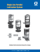
Single Line Parallel Lubrication System Multiple Point Lubrication Using Oil or Grease
L12100 LubriSystem of reservoirs allow a system to be designed precisely for your application. Reservoirs include a fill stud fp reservoir refilling. Automated Centralized Lubrication System that can be used in virtually any application where centralized operation is desired.
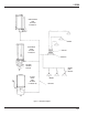
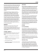
L12100 HAND-OPERATED PUMP SEE PAGES 9 THROUGH 12 BEARING AIR-OPERATED PUMP SEE PAGES 4 THROUGH 8 INJECTOR MANIFOLD SOLENOIDOPERATED AIR VALVE BEARING POINT INJECTOR ELECTRIC MOTOR PUMP SEE PAGES 13 THROUGH 160 BEARING FEED LINES Figure 1.
L12100 SYSTEM OPERATION As shown in Figure 1, when the electic motor or solenoid-operated air valve receives a signal from the timer, or when the operator actuates the handle, the pump is activated. The pump dispenses lubricant either into the mainline tubing which distributes the lubricant to the manifolds, feeding each injector, or to lines supplying bearing point injectors. Each of the injectors is sized to measure and dispense the proper amount of lubricant based on the size of the bearing.
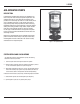
L12100 AIR-OPERATED PUMPS DESCRIPTION LubriSystem air-operated pumps (Figure 2) are available in two lube-to-air power ratios to meet your system requirements. The standard pump has a 9:1 ratio while the high-pressure pump provides a 24:1 ratio. Output per stroke is 1.5 cubic inches (24.59 cm³) for standard pumps and 1.4 cubic inches (22.95 cm³) for high-pressure pumps. Both pump bodies are made from strong, lightweight aluminum and are furnished with a corrosion-resistant coating.
L12100 All reservoirs used with grease are equipped with a spring-loaded follower which provides a positive, air-free supply of grease to the pump. Pumps are equipped with a fill stud and strainer to allow easy filling of the reservoir from a supply source. Oil reservoirs are also equipped with a fill cup and strainer, allowing easy refilling from an oil can. Optional low-level switches, timers and solenoid-operated air valves are available to custom design your application.
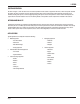
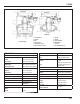
L12100 1 2 RESERVOIR 1 2 RESERVOIR 3 3 9 9 4 5 4 8 5 7 8 12 10 7 11 6 STANDARD 12 1. FLAPPER VALVE 2. SCREEN 3. BALL 4. CHECK VALVE 5. LUBE OUTLET PORT 6. AIR INLET OUTLET PORT 6 HIGH-PRESSURE 7. PISTON 8. SPRING 9. LUBE CHAMBER 10. DIAPHRAGM 11. LIP SEAL 12. AIR CHAMBER CAVITY Figure 3. Air-Operated Pump Operation SPECIFICATION 125 VDC 0.5 amp Pumps: 250 VDC 0.
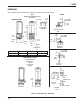
L12100 DIMENSIONS Figure 4 presents layouts of the standard and high-pressure pumps along with common options. NOTE DIMENSIONS SHOWN ARE IN INCHES (MILLIMETERS) STANDARD 9:1 PUMP OPTIONS 0.75 (19.05) 1.00 (25.4) 2.85 (72.9) 3.75 (96.3) 3.25 (82.6) “A” PLASTIC GREASE RESERVOIR 15 AMP GREASE LOWLEVEL 1.75 (44.5) 3.03 (76.9) 0.50 (12.7) 3.563 (90.50) 6.87 DIA. (175) 1/2-14 NPSM COND. CONN. 4.56 (116) 5.063 (129) 3.69 (93.7) 0.343 DIA. (8.71) MNTG. HOLES TYP.
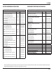
L12100 SYSTEM ORDERING INFORMATION COMPONENT ORDERING INFORMATION LUBRISYSTEM AIR-OPERATED PUMPS Description Part No. LUBRISYSTEM AIR-OPERATED PUMPS COMPONENTS Old Part No. Standard - Oil 563574 550-000-170 Standard Pump (no reservoir) 12 pint (5.68 liter) plastic reservoir 563575 550-000-180 High-Pressure Pump (no reservoir) 20 pint (9.46 liter) plastic reservoir 563576 550-000-190 6 pint (2.
L12100 HAND-OPERATED PUMPS DESCRIPTION The multiple stroke, positive-displacement LubriSystem Hand Pump (Figure 5) delivers 0.125 cubic inches (2.0 cm3) with each stroke of the handle. The LubriSystem Hand Pump is available with standard clear plastic reservoirs for either oil or grease. Modular pump/reservoir design plus built-in features readily tailor the LubriSystem Hand Pump to a wide range of applications. The pump is sturdily built of aluminum and steel in a compact, space-saving package.
L12100 FEATURES / BENEFITS • Interchangeable reservoirs make it easy to customize the pump package for each application. • Simple, positive-displacement pump design keeps the number of wear parts to a minimum for extended pump life. • Built-in bleed mechanism provides system pressure venting when the pump handle is returned to the fully upright position. • 3000 psi pressure gauge provides a fast check on system status.
L12100 DIMENSIONS Figure 7 provides dimensions for the hand-operated pump. DETENT POSITION PRESSURE RELIEF POSITION (FULLY UPRIGHT) 17.03 FULL STROKE (433) 3.91 (99.3) FILL CUP OIL RES’V ONLY 11.0 PUMPING (279) 0.75 (19.05) STROKE 3.25 (82.6) FILL STUD GREASE RES’V ONLY 1.00 (25.4) 15.00 (381) PUMPING RANGE 1.28 (32.52) “A” 2.37 (60.2) 1/4 NPT LUBE OUTLET 11.09 (282) 0-3000 PSI PRESSURE GAUGE RESERVOIR SIZE 6 12 20 A DIMENSION 10.5 (267) 15 (381) 22 (559) Figure 7.
L12100 SYSTEM ORDERING INFORMATION LUBRISYSTEM HAND-OPERATED PUMPS Description Part No. Old Part No. 6 pint (2.84 liter) w/3000 psi gauge – 550-000-430 12 pint (5.68 liter) w/3000 psi gauge 564419 550-000-440 20 pint (9.46 liter) w/3000 psi gauge 564420 550-000-450 6 lb (2.72 kg) w/3000 psi gauge 564421 550-000-460 12 lb (5.44 kg) w/3000 psi gauge 564422 550-000-470 20 lb (9.
L12100 ELECTRIC MOTOR PUMPS FEATURES / BENEFITS DESCRIPTION PUMP FEATURES INCLUDE: The electric motor LubriSystem pump (Figure 8) is a rugged, reliable pump for applications using oil or fluid grease as the lubricant. The motor itself is a high torque, gear-reduction motor operating at 300 rpm and 115 VAC 50/60 Hz. (Other voltages are available.) The motor drives a positive displacement, self-priming gear pump capable of pumping at a rate of 2.0 cubic inches (32.8 cm3) per minute at 1,000 psi (69 bar).
L12100 DIMENSIONS OPTIONS Figure 10 provides dimensions for the electric motor pump. Solid-State Timer If the pump is equipped with the optional solid-state timer. The “on time” and “cycle time” are controlled via screwdriver adjustable pots. A manual run button is integral with the pump to be used for system check and system filling/purging. When depressed it will activate the pump output as long as button is held in. Pressing button will not reset timer.
L12100 WIRING DIAGRAMS FOR ELECTRIC PUMPS WHITE HIRSCHMANN CONNECT OR BLACK BLACK RE D + IGNITIO N GREEN RE D + IGNITIO N GREEN GROUND 12 VA C GREEN WHITE + BATTE RY WHITE + BATTER Y GROUND TO 8-32 SCRE W ON TRANSFORME R BLACK GROUND TO 8-32 SCRE W ON MOUNTIN G BRACKET + VD C - USE TIM E D ELAY F USE 115 VAC - 0.25A 230 VA C - 0.
L12100 PUMP ORDERING INFORMATION EGP - XX – XX – XXX – XX VOLTAGE OPTION V1 - 12 VDC (W/TIMER) V2 - 24 VDC (W/TIMER) V3 - 115 VAC (W/TIMER) V4 - 230 VAC (W/TIMER) V5 - 12 VDC (W/O TIMER) V6 - 24 VDC (W/O TIMER) V7 - 115 VAC (W/O TIMR) SERVICE OPTION OS - OIL SERVICE GS - GREASE SERVICE RESERVOIR OPTION R03 - 6 PINT PLASTIC OIL/LIQUID GREASE R04 - 12 PINT PLASTIC OIL/LIQUID GREASE R05 - 20 PINT PLASTIC OIL/LIQUID GREASE *LOW LEVEL OPTION LL-LOW LEVEL SWITCH (10 WATT) *FOR OIL SERVICE ONLY, OMIT IF
L12100 INJECTORS AND MANIFOLDS DESCRIPTION Oil injectors in two types and grease injectors in one type (Figure 11) are available for use in the lubrication system. The first, a manifold injector, is designed specifically for mounting in the LubriSystem manifold. The second, a bearing point injector, is designed to be mounted at the lubrication point and does not require a manifold. Both injector styles are designed with a unique feature, allowing output capacity to be changed using adjustment spacers.
L12100 INJECTOR OPERATION Note: Although oil and grease injectors operate in the same manner, each design has been optimized for use with its type of lubricant and system operating conditions. Oil injectors are designed for lower viscosity lubricants, higher cycle rates and lower operating pressure. They will not function properly with grease. Grease injectors are designed for grease consistency lubricants, low cycle rates and higher operating pressure.
L12100 INJECTOR CYCLE INDICATOR OPERATION The injector cycle indicators are attached to the output side of aluminum injectors installed in an in-line manifold only. During the lube cycle, they provide a visual indication that the injector has cycled. Figure 13 represents an injector cycle indicator. As the pump pressurizes the injector, the injector piston moves toward the outlet, pushing a measured amount of lubricant toward the lubrication point.
L12100 STAINLESS STEEL MANIFOLD INJECTOR (OIL) ALUMINUM MANIFOLD INJECTOR (OIL OR GREASE) 2.125 (53.97) 0.38 (9.65) HEX 2.125 (53.97) 0.38 (9.65) HEX FOR 3/16 TUBE FOR 1/8 TUBE INJECTOR CYCLE INDICATOR (BRASS) FOR ALUMINUM INJECTOR BEARING POINT INJECTOR (OIL) PLATED CARBON STEEL STAINLESS STEEL 1/8 TUBE INJECTOR 0.969 (24.61) 2.55 (64.77) 1.156 (29.36) 1/8-27 NPSF 1/8-27 NPTF Figure 14.
L12100 DOUBLE-SIDED SINGLE-SIDED 0.875 (22.23) 0.875 (22.23) 0.812 (20.62) TYP. 0.375 (9.53) 0.812 (20.62) 0.375 (9.53) TYPICAL SIDE VIEW B 0.664 (16.87) B TYP. .266 DIA. MTG. HOLES (6.76) 1/4-18 NPSF SUPPLY PORTS D D 0.375 (9.53) 0.375 (9.53) C C 0.203 (5.16) 0.203 (5.16) 1.000 (25.4) 1/2 - 24 (TYP) 1.000 (25.4) SINGLE-SIDED DIMENSION DOUBLE-SIDED DIMENSION HOLE QTY B DIM C DIM D DIM HOLE QTY B DIM C DIM D DIM 8 0.906 (23.01) 3.500 (88.90) 4.250 (108.0) 4 0.906 (23.
L12100 1/4-20 X 1 1/2 1/2 HEX HEAD SCREW (2 SUPPLIED) 0.812 (20.6) (TYP.) 0.75 (19.05) 0.75 (19.05) S M L 0.664 (16.87) 1.00 (25.4) 1/4-18 NPSF BOTH ENDS STAINLESS STEEL NO. OF PORTS S M L PART NO. OLD PART NO. 1 0.625 (15.8) 1.25 (31.7) 1.75 (44.5) 563764 550-401-101 2 0.594 (15.1) 2.0 (50.8) 2.5 (63.5) 563765 550-401-102 3 0.563 (14.3) 2.75 (69.8) 3.25 (82.6) 563766 550-401-103 4 0.532 (13.5) 3.5 (88.9) 4.0 (101.6) 563767 550-401-104 Figure 16.
L12100 ORDERING INFORMATION LUBRISYSTEM MANIFOLD AND ACCESSORIES INJECTOR ACCESSORIES Description Description Part No. Old Part No. Manifolds - Stainless Steel Inlet Adaptor, 1/2-27 in FM x 1/8 in NPSF Female Part No. Old Part No.
L12100 ACCESSORIES/HARDWARE Figure 17. Tubing (unplasticized nylon) Figure 18. Union HEAVYWALL LUBE LINES (TUBING) Description Part No. TEES AND UNIONS Old Part No. Main Line (pump to manifold): 5/16 in OD x .059 wall (7.9 x 1.5), black, 60 ft (18.3 m) 561132 550-450-230 Burst Pressure Min - 1500 psi (103 bar) at 75ºF (24ºC) Description Part No. Old Part No.
L12100 Figure 20. Tubing Straps Figure 22. Harness Clamps TUBING STRAPS HARNESS CLAMPS AND BRACKETS Description Part No. Old Part No. Description Part No. Old Part No. 100 pieces, 11.5 in (292 mm) 563770 550-402-340 5/16 (7.94) diameter 557943 550-400-040 3/8 (9.53) diameter 557946 550-400-070 7/16 (11.11) diameter 557944 550-400-050 1/2 (12.7) diameter 557947 550-400-080 5/8 (15.22) diameter 557945 550-400-060 Description Part No. Old Part No.
HOW-TO-ORDER LUBRISYSTEM ANALZING SYSTEM REQUIREMENTS FOR MORE INFORMATION 1. Determine individual bearing requirements. Graco literature No. L20115 provides a procedure for calculating the lubricant volume requirement for individual lube points. Literature No. L20102 - LubriSystem Design Guide. Guidelines and information for LubriSystem component selection and design calculation charts. 2. Analyze bearing locatoins and group those that can conveniently fed from a single manifold.