
User's Manual
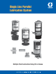


L12100
All reservoirs used with grease are equipped with a spring-loaded
follower which provides a positive, air-free supply of grease to the
pump. Pumps are equipped with a fi ll stud and strainer to allow
easy fi lling of the reservoir from a supply source. Oil reservoirs
are also equipped with a fi ll cup and strainer, allowing easy
refi lling from an oil can. Optional low-level switches, timers and
solenoid-operated air valves are available to custom design your
application.
The solenoid-operated air valve, designed for use with air-
operated pumps, is controlled by a solid-state timer or other
electronic controller. The solenoid is a 115 VAC, three-way,
normally-closed valve with a manual override. The manual
override simplifi es system testing, line fi lling, and line bleeding
by allowing the operator to control when the pump dispenses
lubricant. When the solenoid receives a 115 VAC signal from its
controller, it actuates the valve to allow air fl ow to the pump. While
the solenoid is energized, the pump strokes forward sending
lubricant through the system. When the solenoid is de-energized,
the pump piston returns. An FR unit (FRL with high pressure
pumps) must be used upstream of the air valve to remove harmful
dirt and water from the air supply. Air pressure should be a
maximum of 100 psi (7 bar) for the high-pressure pump or 150
psi (10 bar) for standard pumps.
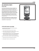
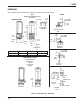
MOUNTING
Sturdy bracket, with four mounting holes, holds pump with
solenoid and reservoir. Assembly should be mounted in a
protected, centralized, and readily accessible location. Pump must
be mounted in a vertical position only, with reservoir up. Use four
5/16 inch or M8 machine screws at the mounting holes to ensure
secure placement.
FEATURES / BENEFITS
Proven dependable performance. Many pumps now in use have
logged over 5 years of trouble-free operation. Pump features
include:
• Simple design—few moving parts results in less wear and
downtime.
• Compact modular construction allows you to customize the
pump/reservoir design to fi t your application.
• Lube supply status at a glance.
• Rugged aluminum construction to provide lightweight features
with heavy-duty capabilities.
OPERATION
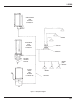
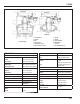
Figure 3 portrays the air-operated pumps in the “at-rest” position.
The fi gure represents both standard and high-pressure pumps.
The description of operation applies to both. At this point, air is
not present and spring (8) pressure has moved piston (7) to the
down position. When the piston is down, fl apper valve (1) opens
and lubricant from reservoir fi lls lube chamber (9) above the
piston. Spring pressure on check valve (4) prevents lubricant from
fl owing through the outlet port. This condition also allows residual
pressure in the lube lines to raise ball (3), pass through screen (2)
and return to the reservoir. This venting of the output lines allows
injectors to prime themselves.
When air at 40 to 100 psi (3 to 7 bar) is applied to air inlet port
(6), pressurized air fi lls air chamber cavity (12), forcing piston
(7) upward, pressurizing lubricant in lube chamber (9). The
pressurized lubricant closes fl apper valve (1) (preventing the
discharge lubricant from being fed back to the reservoir) and
forces check valve (4) open, allowing lubricant to fl ow through
lube outlet port (5) to the injectors. When air pressure is removed,
spring (8) returns piston (7) to the down position to repeat the
cycle. On the standard pump a diaphragm (10) is used to seal
the air chamber cavity (12), on the high-pressure pump, this is
accomplished by a lip seal (11).
OPTIONS
Low-Level Switches
Several assemblies are available to provide a signal when the
lubricant level is low. Low-level switch assemblies used on oil
reservoirs depend on fl oats that fall with the depletion of lubricant
and actuate contacts on the switch. Switch assemblies used
on grease reservoirs are actuated when a cable attached to the
grease follower is pulled away from the switch as the follower
reaches the low position. Limit switch assemblies used on grease
reservoirs are rated at 15 amps. Oil reservoirs use 10-watt reed-
type switches.
The low-level assemblies with a 15 amp rating are often used
to activate a warning device such as light or alarm. The 10-watt
assemblies are used to provide input to controllers which may be
programmed to use the input signal as desired.
Solid-State Timer
This solid-state timer can be used to initiate pump cycles
on a time basis at intervals from 1/2 minute to 32 hours. A
built-in memory retains the cycle time for 1-1/2 hours during
power failure or machine shutdown to resume from the point
where it was suspended. For details, see Literature No. 14521.
Sophisticated multi-function controllers are also available for use
in systems using pressure switches. Refer to literature No. 14540
(LC-1000) and 14750 (WMP III).
Page 5