
User's Manual


L12100
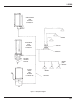
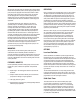
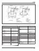
Figure 3. Air-Operated Pump Operation
RESERVOIR
RESERVOIR
1
2
3
3
2
4
9
5
10
6
12
8
7
4
5
9
6
12
8
7
11
1
HIGH-PRESSURE
STANDARD
1. FLAPPER VALVE
2. SCREEN
3. BALL
4. CHECK VALVE
5. LUBE OUTLET PORT
6. AIR INLET OUTLET PORT
7. PISTON
8. SPRING
9. LUBE CHAMBER
10. DIAPHRAGM
11. LIP SEAL
12. AIR CHAMBER CAVITY
Page 6
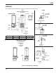
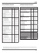
SPECIFICATION
Pumps:
Air Inlet Pressure
Stadard 40 to 150 psi (3 to 10 bar)
High-Pressure 40 to 100 psi (3 to 7 bar)
Lube Outlet Pressure
Standard (9:1) 360 to 1350 psi (25 to 93 bar)
High-Pressure (24:1) 960 to 2400 psi (66 to 165 bar)
Pump Output per Stroke
Standard 1.5 cu.in. (24.59 cm
3
)
High-Pressure 1.4 cu.in. (22.95 cm
3
)
Air Inlet Port 1/4-18 NPSF
Lube Outlet Port 1-4/18 NPSF
Operating Temperatures (w/NLGI #1) 40ºF to 135ºF (4ºC to 50ºC)
Lubricant Oil or Grease (NLGI #1 or lighter)
Type
Air-actuated positive
displacement
Low-Level Switches:
Grease or Oil Reservoir 15 amp
Switch
115 VAC 15 amp
125 VDC 0.5 amp
250 VDC 0.25 amp
Type Single-pole, double-throw
Oid Reservoir Only - 10 Watt
115 VAC 10 Watt
Type
Single-pole, single-throw reed
type switch, normally-open or
normally closed
Solid-State Timer:
Electrical 115 VAC, 50/60 Hz, 3 amp (max)
Temperature range - Operating
Storage
0ºF to 131ºF (-18ºC to 55ºC)
-67ºF to 185ºF (-55ºc to 85ºC)
Enclosure High Impact Plastic
Component Technology Solid-State CMOS
Cycle Frequency, Adjustable
Range 1 1/2 min to 30 mins
Range 2 1/2 hour to 32 hours
“On” Time 0.2 min to 13 mins
Standard; LED Indicator, Manual Run
Buttom; Vibrations
5g’s, 50 Hz