Modu-Flo® System LUBRIQUIP® BY Operation and Service Instructions Bulletin 42000 R © LUBRIQUIP, INC., 1988. All Rights Reserved.
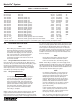
Modu-Flo® System 42000 TABLE OF CONTENTS Section/Para 1 1.1 1.2 Page INTRODUCTION .............................................. 1-1 Section/Para 5.3 GENERAL ............................................................. 1-1 GENERAL SYSTEM OPERATION ......................... 1-2 5.4 2 2.1 2.2 2.3 2.4 2.5 2.6 3 3.1 3.2 3.3 3.4 3.5 4 4.1 4.2 4.3 5 5.1 5.2. RESERVOIRS AND TANKS ............................. 2-1 DESCRIPTION ......................................................
Modu-Flo® System 42000 Assemblies Parts List ........................................ 5-3 LIST OF TABLES Number 2-1. 2-2. 2-3. 2-4. 3-1. 3-2. 3-3. 3-4 4-1. 4-2. 5-1. 5-2. Title Page Reservoirs and Tanks ......................................... 2-2 Grease Reservoir Parts List ............................... 2-4 Oil Reservoir Parts Lists ..................................... 2-8 Oil Tank Parts List ............................................. 2-12 Pumps ................................................
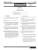
Modu-Flo® System 42000 OPERATION AND SERVICE INSTRUCTIONS Modu–Flo® System SECTION 1 INTRODUCTION 1.1 GENERAL ................................................................... 1-1 1.1.1 Standard Components ................................... 1-1 1.1.2 Modu-Flo Options ........................................... 1-1 1.2 GENERAL SYSTEM OPERATION .............................. 1-1 1.1 GENERAL 1.1.1 Standard Components. A wide choice of modular components may be assembled to meet a given application.
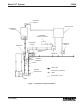
Modu-Flo® System 1.2 42000 c. A controller energizes a solenoid valve to dispense and the solenoid sends air or hydraulic fluid to the manifold. Porting in the manifold directs the air or hydraulic fluid to the pump, causing the pump to dispense lube to the manifold outlet port. d. Lubricant stored in the reservoir or tank flows to the manifold. The manifold may be mounted directly to the reservoir or tank, or it may be mounted on a wall.
Modu-Flo® System 42000 LOW LEVEL SWITCH CONTROLLER RESERVOIR OR TANK PNEUMATIC/ HYDRAULIC SUPPLY SYSTEM FILL CHECK MANIFOLD PRESSURE SWITCH LUBE OUTLET CHECK SOLENOID BLOWOUT ASSEMBLY GAUGE LUBE LINES TEST/AIR PURGE PORT PNEUMATIC/HYDRAULIC LINES ELECTRICAL LINES PUMP Figure 1-1.
Modu-Flo® System 42000 OPERATION AND SERVICE INSTRUCTIONS Modu–Flo® System SECTION 2 RESERVOIRS AND TANKS 2.1 DESCRIPTION .......................................................... 2-1 2.4.5 Grease Reservoir Parts Lists ....................... 2-3 2.1.1 Reservoir Description ................................... 2-1 2.1.2 Tank Description ........................................... 2-1 2.1.3 Reservoirs and Tanks Available ................... 2-1 2.5 OIL RESERVOIR MAINTENANCE (OPTIONS OP1 THROUGH OP4) ..
Modu-Flo® System 42000 Table 2-1.
Modu-Flo® System ounces of heavy oil through the grease fill quick disconnect. The pump will then prime on oil pulling the grease behind it. If it becomes necessary to use this method, all injected oil should be discharged at the loosened system supply connection along with any air. 42000 the chance of spillage. The disassembly procedure is as follows: WARNING Do not attempt to remove retaining ring (2) or cable assembly (5) (Figure 2-1) (or retaining ring (25) or guide rod (5) for Option GP5).
Modu-Flo® System 42000 Table 2-2. Grease Reservoir Parts List Item Number 1 Part Number Description 185-100-040 185-100-000 185-100-010 185-100-760 185-101-080 185-100-050 185-100-020 185-100-030 185-100-770 415-700-272 RESERVOIR ASSEMBLY, RESERVOIR ASSEMBLY, RESERVOIR ASSEMBLY, RESERVOIR ASSEMBLY, RESERVOIR ASSEMBLY, RESERVOIR ASSEMBLY, RESERVOIR ASSEMBLY, RESERVOIR ASSEMBLY, RESERVOIR ASSEMBLY, BOLT, Tie (5 lb., 12 lb.) 415-700-271 415-700-273 415-020-190 Quantity 5 lbs (2.27 kg), 12 lbs (5.
Modu-Flo® System 42000 Table 2-2. Grease Reservoir Parts List - Continued Item Number 20 21 22 23 24 25 26 27 28 Part Number Description 439-060-181 GASKET, Top Vent (3 lb.) BUSHING, Follower WASHER, Follower WASHER, Support NUT, Jam, 3/4-16 O-RING RING, Retaining PLUG, Low Level (3 lb.) GASKET (3 lb.) 527-000-230 527-000-240 Quantity 1 1 1 1 1 1 1 1 1 Items 21 through 26 are not serviceable by the user; replace entire reservoir.
Modu-Flo® System 2.5 OIL RESERVOIR MAINTENANCE (OPTIONS OP1 THROUGH OP4) 2.5.1 General. Maintenance tips, disassembly, and assembly procedures for oil reservoirs are discussed in Paragraphs 2.5.2, 2.5.3 and 2.5.4. An exploded view of a typical oil reservoir is shown in Figure 2-2 and should be referred to during the discussion. 2.5.2 Oil Reservoir Maintenance. 2.5.2.1 Maintenance on the oil reservoir consists of the following: a. b. c.
Modu-Flo® System 42000 Table 2-3.
Modu-Flo® System 42000 1 2 3 4 5 6+ B DIMENSIONS OPTION 7.25 inches (184 mm) 15 inches (381 mm) OP3 7.25 inches (184 mm) 22 inches (559 mm) OP4 7.25 inches (184 mm) 10.5 inches (267 mm) 8 4 B OP1, OP2 A 7 A 4 10 9 + Reservoir Tube Kit includes gasket (Item 7). Figure 2-2.
Modu-Flo® System 2.6 OIL TANK MAINTENANCE (OPTIONS T1, T2 and T3) 2.6.1 General. Maintenance tips, disassembly and assembly procedures for oil tanks are discussed in Paragraphs 2.6.2, 2.6.3 and 2.6.4. An exploded view of a typical oil tank is shown in Figure 2-3 and should be referred to during the discussion. 2.6.2 42000 b. Remove self-threading screws (2) attaching cover (1) to tank weldment (9) and remove cover and cover gasket (6). c. Remove fill screen (4) from fill cup (5) and clean screen. d.
Modu-Flo® System 42000 Table 2-4.
Modu-Flo® System 42000 3 4 2 15 1 6 5 7* * 8* 14 A Reservoirs with separate aluminum pump mounting pads only. Steel pump mounting pads are welded in place and are not replaceable. + Used on reservoirs with front pressure-fill 9 port only. 16+ 10 11 C 13* 3 DIMENSIONS B 12* OPTION A B C T1 10.75 inches (273 mm) 7.25 inches (184 mm) 10.70 inches (272 mm) T2 12 inches (305 mm) 13.22 inches (336mm) 10.59 inches (269 mm) T3 17.25 inches (438 mm) 13.22 inches (336 mm) 10.
Modu-Flo® System 42000 OPERATION AND SERVICE INSTRUCTIONS Modu–Flo® System SECTION 3 PUMPS 3.1 DESCRIPTION .......................................................... 3-1 3.1.1 General .......................................................... 3-1 3.4.3 Disassembly of Hydraulic Pump Options H1 and H3 ....................................... 3-9 3.4.4 Assembly of Hydraulic Pump Options H1 and H3 ........................................................... 3-9 3.4.
Modu-Flo® System 42000 3.1.1.4 In pneumatically-operated systems, pressure surges often occur when the solenoid is energized. These surges can be minimized by installing air flow devices in the solenoid pneumatic lines. double-acting. Listings in the option column are used to identify the pump selected when a Modu-Flo system is ordered. The option used is designated by the entry in the ordering code as shown below: 3.1.1.5 Table 3-1 lists the available pumps along with other data.
Modu-Flo® System 3.2 PREPARATION FOR USE 3.2.1 Mounting. Any pump mounts directly to any manifold with four socket-head capscrews. Care must be taken to ensure that the outlet of the manifold is lined up with the inlet on the pump. The face of the pump which mates with the manifold has several o-rings. When the pump is being installed, care must be taken to ensure these o-rings are not moved out of position. The o-rings provide a seal for the movement of air and lubricant between the manifold and pump.
Modu-Flo® System e. f. Insert wooden dowel or soft rod into pump body (10) and push lube piston (5) until cylinder cap (3) is out of air cylinder (7). Remove and discard o-ring (2) from cylinder cap (3). Continue to push lube piston (5) through pump body (10) until air piston (1) is exposed and can be removed from air cylinder (7). Remove air piston (1), lube piston (5), and piston-return spring (24) from air cylinder (7). g. Remove retainer ring (25) and spring retainer (26) from air piston (1). h.
Modu-Flo® System 42000 Table 3-2.
Modu-Flo® System 42000 Table 3-2.
Modu-Flo® System 42000 4+ 3 2+ 1 5* 6+ 24 + 28 + 27 + 26 25 + 23 19 ** 7 36+ 20 + 21 + 20 + 18 + 22 14 15 + 16 + 17 + 9+ 30 + 8+ 29 + 9+ *** TEST/AIR PURGE PORT 34 + 33 ‘ 6 35+ 15 + 16 + 17 + 6 10* 12 + 11 + 13** CHECK VALVE COMPONENTS PREVIOUS TO L93 Not Available as Replacement Parts. (December 1993) Included in Repair Kit. Refer to Page 3-6. Included in Pump Adjustment Assembly. Refer to Page 3-6. * + ** *** SEE NOTE ON PAGE 4.2 Figure 3-2.
Modu-Flo® System 3.4 42000 (2) Remove jam nut (19) and two gaskets (18). Discard gaskets (18). HYDRAULIC PUMP MAINTENANCE (OPTIONS H1 and H3) 3.4.1 General. Maintenance tips, disassembly and assembly procedures for Options H1 and H3 hydraulic pump are discussed in Paragraphs 3.4.2 through 3.4.4. An exploded view of the pump is shown in Figure 3-3 and should be referred to during the discussion. 3.4.2 Tips.
Modu-Flo® System f. 42000 Install jam nut (19) and two new gaskets (18), one on each side of jam nut, on adjustment screw (10). Butt adjustment screw cap (20) against jam nut (19) and turn adjustment screw (10) until the length it extends beyond the jam nut is the same as the length recorded during disassembly. g. Install adjustment screw cap (20) on adjustment screw (10). h. Install new o-ring (23) on check seat (22) and install seat assembly into pump body. i.
Modu-Flo® System 42000 6 5+ FOR H1 OPTION (HLJ-5) 3+ 4+ 26+ 2 25+ 1 29+ 21+ 27* 17 FOR H3 OPTION (HLJ-5X) 28+ 18+ 19 18+ 16+ 20 11 12+13+ 14+ 15+ 23+ 22+ *** TEST/AIR PURGE PORT 7* 31 ‘ 6 32 6 30 12+ 13+ 14+ 9+ 10 8 CHECK VALVE COMPONENTS PREVIOUS TO L93 (December 1993) * Not Available as Replacement Parts. + Included in Repair Kit. Refer to Page 3-10 for Repair Kits *** SEE NOTE ON PAGE 4.2 Figure 3-3.
Modu-Flo® System 3.5 42000 sembled. If adjustment screw (13) requires removal, perform the following: HYDRAULIC PUMP MAINTENANCE (OPTION H2) (1) Remove adjustment screw cap (22) from adjustment screw (13). Butt the adjustment screw cap (21) against jam nut (22) and use the stamped numbers on the cap to measure how far the adjustment screw (13) extends from the jam nut. Record this dimension. 3.5.1 General.
Modu-Flo® System 42000 Place new gasket (15) on enclosure screw (14). Screw enclosure screw (14) into body (10) and tighten securely. i. Install three new o-rings (9) and one new o-ring (18) into body (10). Securely attach pump to manifold using four socket-head screws (11). 3.5.4.2 When the assembly steps listed above have been completed, adjust the pump output as described in Paragraph 3.2.2. 3.5.5 Hydraulic Pump Option H2 Parts List. Table 3-4 identifies the parts indexed in Figure 3-4. Table 3-4.
Modu-Flo® System 42000 6 5+ 4+ 3+ 2 24+ 1* 9+ 7 23 33+ 19 18+ 20+ 8+ 27+ 21+ 14 20+ 15+ 16+ 17+ 26+ 25+ 27+ 22 *** TEST/AIR 10* PURGE PORT ‘ 6 31+ 32+ 16+ 17+ 6 15+ 12+ 13 11+ * Not Available as Replacement Parts. + Included in Repair Kit. Refer to Page 3-14 for Repair Kits *** 30 CHECK VALVE COMPONENTS PREVIOUS TO L93 (December 1993) SEE NOTE ON PAGE 4.2 Figure 3-4.
Modu-Flo® System 42000 OPERATION AND SERVICE INSTRUCTIONS Modu–Flo® System SECTION 4 MANIFOLDS 4.1 DESCRIPTION ........................................................... 4-1 4.1.1 General ........................................................... 4-1 4.2 PREPARATION FOR USE .......................................... 4-1 4.2.1 Mounting ......................................................... 4-1 4.2.2 Connection to Other Components ................. 4-1 4.3 MAINTENANCE .................................
Modu-Flo® System Table 4-1. Operating Ports on Modu-Flo Manifolds 42000 Table 4-2. Manifolds and Manifold Accessories Port Name Function Item Part Number DA (Double Acting) Single-acting model pumps: Port is fitted with a plastic vent orifice plug so that air can be exhausted on piston return stroke. Double acting model pumps: Port has air or hydraulic supply connected to it. Fluid directed to this port causes the pump to retract to the loading position.
Modu-Flo® System 42000 O-RING P/N 422-010-210 SINGLE ACTING (S.A.) PORT LUBE SYSTEM OUTLET PLUNGER LUBE SYSTEM FILL CHECK VALVE * BLOWOUT ASSEMBLY DOUBLE ACTING (D.A.) PORT YELLOW VENT PLUG ** TEST/AIR PURGE PORT * This port is used to manually fill system lube lines. This is not the reservoir fill port. See figure 2-1 on page 2-5, item 15 for location of grease reservoir fill. ** On newer units, the test port has been relocated to the adjustment end of the pump body.
Modu-Flo® System 42000 OPERATION AND SERVICE INSTRUCTIONS Modu–Flo® System SECTION 5 LOW-LEVEL SWITCHES 5.1 DESCRIPTION .......................................................... 5-1 5.1.1 General .......................................................... 5-1 5.2. MOUNTING INSTRUCTIONS ................................... 5-1 5.2.1 Oil Reservoirs and Tanks .............................. 5-1 5.2.2 Grease Cylinders .......................................... 5-1 5.
Modu-Flo® System 42000 Table 5-1.
Modu-Flo® System c. 42000 Screw low-level lower assembly (4) into low-level adapter (3) and tighten securely. e. Screw switch adapter (2) into switch (1) and tighten securely. f. Screw union nut (5) onto switch adapter (2) and tighten securely. g. Install cover on reservoir (Refer to Section 2.). h. Wire switch in accordance with local electrical codes.
Modu-Flo® System 5.4 OIL TANK RESERVOIR 10-WATT LOW-LEVEL ASSEMBLY MAINTENANCE (OPTIONS L5, L6 AND L7) 5.4.1 General. Maintenance tips, disassembly and assembly procedures for low-level options L5, L6 and L7 are discussed in Paragraphs 5.4.2, 5.4.3 and 5.4.4. A sectional view of a low-level assembly is shown in Figure 52 and should be referred to during the discussion. 5.4.2 Oil Tank and Reservoir 10-Watt Low-Level Assembly Maintenance Tips.
Modu-Flo® System 42000 Table 5-3. Oil Tank and Reservoir 10-Watt Low-Level Assemblies Parts List Item Number 1 Part Number Description 456-010-172 456-010-173 456-010-171 LOW-LEVEL ASSEMBLY LOW-LEVEL ASSEMBLY LOW-LEVEL ASSEMBLY 541-603-001 541-603-002 SWITCH, 10 watts, 115 VAC, NC SPST OPTIONAL SWITCH, 10 watts, 115 VAC, NO, SPST COUPLING NIPPLE ADAPTER 2* 3* 4* Quantity (5 pint, 12 pint) (20 pint) (6 pint) ---1 1 1 1 Figure 5-2.
Modu-Flo® System 42000 a. Disconnect and lock out all electrical power and air supplies to the lube system. a. Attach bracket (2) to grease reservoir cover using three self-tapping screws (4). b. Disconnect switch (1, Figure 5-3) from terminal box. Remove switch (1) from bracket (2). b. Place spring (5) over tip of level indicator. c. c. Remove retainer ring (3) and spring (5). Compress spring (5) and place retainer ring (3) between spring and tip of level indicator. d.
Modu-Flo® System 42000 OPERATION AND SERVICE INSTRUCTIONS Modu–Flo® System SECTION 6 HIGH-PRESSURE AND BLOWOUT SWITCHES 6.1 DESCRIPTION .......................................................... 6-1 6.1.1 High-Pressure Switches ............................... 6-1 6.1.2 Blowout Switches .......................................... 6-1 6.1.3 Blowout Disc ................................................. 6-1 6.1.4 High-Pressure and Blowout Switch Options .......................................................
Modu-Flo® System 42000 6.1.3.1 When any pressure or blowout switch is actuated, personnel must determine the cause for the rise in pressure. After the cause has been corrected, any blowout discs which have been ruptured will need to be replaced with an approved disc. 6.1.4 High-Pressure and Blowout Switch Options. Table 6-2 lists the pressure and blowout switch options available for use. Listings in the option column are used to identify the assembly selected when a Modu-Flo system is ordered.
Modu-Flo® System 42000 Table 6-3. Pressure Switch Settings Disc Rating psi (bar) Disc Color Yellow Red Orange Aluminum Blue Purple 1450 (100) 1750 (121) 2050 (141) 2350 (162) 2950 (203) 3250 (224) Maximum Recommended Pressure Switch Setting psi (bar) 6.3 MOUNTING INSTRUCTIONS 6.3.1 All high-pressure switches and blowout options are connected to the outlet of the manifold and mounted to various locations on the reservoir or tank. Refer to assembly Paragraphs 6.4.3, 6.5.3 and 6.6.
Modu-Flo® System 42000 Table 6-4. High-Pressure Switch Parts List Index Number 1 2 3 4 5 6 Part Number Description Quantity 521-001-220 HIGH-PRESSURE SWITCH ASSEMBLY (Option P1) -- 542-210-120 412-380-020 509-206-100 ---- SWITCH, Pressure TEE, Male, 1/4 inch pipe BLOWOUT ASSEMBLY, 1450 psi . FITTING, Adapter . DISC, Blowout . NUT, Pressure relief 1 1 1 1 1 1 IND PORT TANK OR RESERVOIR S.A. MANIFOLD (REF) 6 5 3 Figure 6-2.
Modu-Flo® System 42000 Table 6-5. Reservoir Blowout Switch Parts List Item Number 1 2 3 4 5 6 7 8 9 10 11+ 12 13 14 15 16 17 18 --19 Part Number Description 521-001-190 521-001-200 521-000-760 521-000-770 416-701-992 HIGH-PRESSURE BLOWOUT SWITCH ASSEMBLY (5 pint/lb) HIGH-PRESSURE BLOWOUT SWITCH ASSEMBLY (6, 12 or 20 pint/lb) BRACKET, Mounting, for 5 lb and 5 pt BRACKET, Mounting, for 6 lb, 12 lb, 20 lb, 6 pt, 12 pt, and 20 pt SCREW, Round head, 6-32 x 1-3/8 inch, part of Part No.
Modu-Flo® System 6.6 42000 TANK BLOWOUT SWITCH MAINTENANCE (OPTION P4) 6.6.1 General. Maintenance tips, disassembly, and assembly instructions for tank blowout switches are discussed in Paragraphs 6.6.2 and 6.6.3. A typical tank with blowout switch is shown in Figure 6-4 and should be referred to during the discussion. 6.6.2 Tank Blowout Switch Maintenance Tips. No maintenance is required on the blowout switch.
Modu-Flo® System 42000 6 PLUNGER 1 2,3,4 5 7 8 9 16 1,13,14,15 12 11 10 Figure 6-4.
Modu-Flo® System 42000 Modu–Flo® System OPERATION AND SERVICE INSTRUCTIONS SECTION 7 PNEUMATIC SOLENOID 7.1 DESCRIPTION ........................................................... 7-1 7.2 OPERATION ............................................................... 7-1 7.3 INSTALLATION ........................................................... 7-1 7.1 DESCRIPTION The Pneumatic Solenoid Valve option S1 is designed for use in 115 VAC applications, while the S2 option is for 24 VDC applications.
Modu-Flo® System 42000 OPERATION AND SERVICE INSTRUCTIONS Modu–Flo® System SECTION 8 CONTROLLERS 8.1 DESCRIPTION .......................................................... 8-1 8.1.1 8.1.2 8.1.3 8.1.4 8.1 DC Timer ....................................................... 8-1 AC Timer ........................................................ 8-1 TC-1000 Timer/Counter ................................ 8-1 WMP Maxi-Monitor ......................................... 8-1 DESCRIPTION 8.1.1 DC Timer.
Modu-Flo® System (–) 42000 12 to 32 VDC POWER SOURCE (+) SWITCH RED (+) BLUE (+) ORANGE TIMER (MEMORY) YELLOW ( – ) BLACK SOLENOID GROUND Figure 8-1. DC Timer Wiring Schematic INSTALLATION INSTRUCTIONS 1. DISCONNECT INPUT AND LOAD POWER SUPPLIES AT THEIR SOURCE. 2. REMOVE (2) SCREWS AND LIFT OUT CIRCUIT BOARD 3. INSTALL 1/2“ CONDUIT CONNECTOR IN .840 DIAMETER HOLE. 4. CONNECT INPUT POWER LEDS TO INPUT TERMINALS. 110/220 VAC 50/60 HZ. 5. CONNECT LOAD LEADS TO LOAD TERMINALS.
Modu-Flo® System 42000 CAUTION: INPUT VOLTAGE WILL BE PRESENT ON TERMINAL - 5 FOR DC MODELS ONLY.
Modu-Flo® System 42000 OPERATION AND SERVICE INSTRUCTIONS Modu–Flo® System SECTION 9 SYSTEM OPERATION 9.1 GENERAL ................................................................. 9-1 9.2 SYSTEM INFORMATION ........................................... 9-1 9.2.1 System Setup ................................................ 9-1 9.2.2 System Filling ................................................ 9-1 9.2.3 System Bleeding ........................................... 9-1 9.2.4 System Start-up ................
Modu-Flo® System 42000 MATERIAL CONSIDERATIONS erratic pump operation and costly parts replacement. Make sure that lubricant used to fill the system is clean. If there is doubt about cleanliness, lubricant should be filtered before being introduced into the system. After filtering the system, make sure the lubricant supply is protected from debris.
Modu-Flo® System 42000 OPERATION AND SERVICE INSTRUCTIONS Modu–Flo® System SECTION 10 TROUBLESHOOTING 10.1 GENERAL ............................................................... 10-1 10.1 GENERAL 10.1.1 Many system problems may be caused by loose connections or air trapped in the system. Before removing system components, it is a good practice to check all connections to make sure they are tight. Also make sure the system is properly bled.
Modu-Flo® System 42000 Table 10-1. Modu-Flo Troubleshooting - Continued Problem Possible Cause Corrective Action D. Pump is not receiving signal to operate. 1. Electrical connections to solenoid or timer are defective. 1. Check all connections and tighten securely. 2. Timer or controller is set incorrectly or is defective. 2. Set timer or controller to correct setting. If unit is still not functioning consult factory for assistance. 3. Pneumatic or hydraulic power supply is turned off. 3.
Bulletin 42000 Trabon® Modu-Flo® System www.lubriquip.com/pdf/42000.pdf Look to LUBRIQUIP, Inc. for all of your Centraliz ed Lubrication System needs. Products include: DIVIDER VALVES: for oil and grease...to 7500 PSI... 1 to 20 points form a single valve assembly...up to 400 points from a Master/Secondaries circuit...or systems that handle an entire plant. PUMPS: fixed and variable displacement...manual and air, hydraulaic, electric motor or mechanically driven.