Instructions/Parts List Triton® 3D150 Diaphragm Pump 311688D Used to pump waterborne and solvent-based paints and catalysts. Part No. 253704, Series B 3:1 Ratio Air-operated Double Diaphragm Pump, with BSPP Fittings Part No. 253705, Series B 3:1 Ratio Air-operated Double Diaphragm Pump, with NPT Fittings 100 psi (0.7 MPa, 7 bar) Maximum Air Input Pressure 300 psi (2.1 MPa, 21 bar) Maximum Fluid Working Pressure Important Safety Instructions Read all warnings and instructions in this manual.
Contents Warning . . . . . . . . . . . . . . . . . . . . . . . . . . . . . . . . . . . 3 Installation . . . . . . . . . . . . . . . . . . . . . . . . . . . . . . . . 5 General Information . . . . . . . . . . . . . . . . . . . . . . 5 Tightening Threaded Fasteners Before First Use 5 Mounting the Pump . . . . . . . . . . . . . . . . . . . . . . . 6 Air Line . . . . . . . . . . . . . . . . . . . . . . . . . . . . . . . . 7 Fluid Suction Line . . . . . . . . . . . . . . . . . . . . . . . . 7 Fluid Outlet Line .
Warnings Warnings The following warnings are for the setup, use, grounding, maintenance, and repair of this equipment. The exclamation point symbol alerts you to a general warning and the hazard symbol refers to procedure-specific risk. Refer back to these warnings. Additional, product-specific warnings may be found throughout the body of this manual where applicable. Warning EQUIPMENT MISUSE HAZARD Equipment misuse can cause the equipment to rupture or malfunction and result in serious injury.
Warnings Warning TOXIC FLUID HAZARD Hazardous fluid or toxic fumes can cause serious injury or death if splashed in the eyes or on the skin, inhaled, or swallowed. • • • • Know the specific hazards of the fluid you are using. Store hazardous fluid in an approved container. Dispose of hazardous fluid according to all local, state and national guidelines. Always wear protective eyewear, gloves, clothing and respirator as recommended by the fluid and solvent manufacturer.
Installation Installation General Information • • • FIG. 2 is only a guide for installing system components and accessories. It is not an actual system design. Contact your Graco distributor for assistance in designing a system to suit your particular needs. Always use Genuine Graco Parts and Accessories, available from your Graco distributor. If you supply your own accessories, be sure they are adequately sized and pressure-rated for your system.
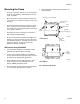
Installation Mounting the Pump • For ease of operation and service, mount the pump so the air inlet, fluid inlet, and fluid outlet ports are easily accessible. • Mount the pump in a well-ventilated area with sufficient clearance on all sides for operator access and servicing. • The pump must be mounted horizontally as shown in FIG. 1. Be sure that the pump is level in all directions and that the cylinder housing (54) is positioned on the bottom. See FIG. 1.
Installation Air Line • For maximum suction lift (wet and dry) information, see Technical Data on page 24. 1. Install the air line accessories as shown in FIG. 2. Be sure the air line supplying the accessories is grounded. • Use an agitator to prevent fluid from settling out. Part number 245081 Agitator Kit (accessory) is available. a.
Installation Key: A B C D E F G H J K L M N P R S T U W TRITON 3D150 Pump Bleed-type master air valve (required for pump) Air supply line Air line filter Air line shutoff valve Pump air regulator Gun air regulator (used in spray system only) Fluid pressure regulator (used in spray system only) Drain/circulation valve Drain tube Suction tube Pump fluid inlet Pump fluid outlet Fluid hose (shown connected to gun in spray system) Gun air hose (used in spray system only) Spray gun (used in spray system only)
Installation Grounding • All fluid pails used when flushing: Follow your local code. Use only conductive metal pails placed on a grounded surface. Do not place the pail on a nonconductive surface, such as paper or cardboard, which interrupts the grounding continuity. Before operating the pump, ground the system as explained below. Read the warnings on page 3. Ground all of this equipment: X • Pump: use a ground wire and clamp. See FIG. 3. Loosen the grounding screw (X). Insert one end of a 12 ga (1.
Operation Operation Pressure Relief Procedure 4. Place the end of the fluid hose (P), see FIG. 2, into an appropriate container. 5. Close the fluid drain valve (J). 6. With the pump air regulator (F) closed, open the bleed-type master air valve (B). Read the warnings on page 3, and follow the Pressure Relief procedure below whenever you: • • • • are instructed to relieve pressure stop spraying check or service any of the equipment install or clean the fluid nozzle. 1. Shut off the air to the pump. 2.
Maintenance Maintenance Lubrication Tightening Threaded Connections CAUTION Lubrication of the pump is not required. Oil is exhausted through the muffler, which could contaminate the fluid supply or other equipment. Excessive lubrication can also cause the pump to malfunction. 1. Before each use, check all hoses for wear or damage, and replace as necessary. 2. Check to be sure all threaded connections are tight and leak-free. Flushing and Storage 3.
Troubleshooting Troubleshooting Relieve the pressure (page 10) before checking or servicing the equipment. Problem Check all possible problems and causes before disassembling the pump. Cause Solution Pump cycles at stall or fails to hold pressure at stall. Worn check valve balls (26), seats (31), or ball guides (32). Replace. See page 20. Pump will not cycle, or cycles once and stops. Stuck or dirty air valve. Disassemble and clean air valve. See page 16. Use filtered air.
Repair Repair Prepare the Pump for Repair Fault Indications 1. Flush the pump if possible, page 11. During operation, check for indications of worn or damaged parts, such as: 2. Relieve the pressure, page 10. 3. Disconnect the air and fluid hoses. 4. Remove the pump from its mounting and take it to the work bench. General Repair Notes • A qualified technician should make all repairs. • Inspect and clean all parts thoroughly before reassembly.
Repair Replace the Diaphragms d. Grip the cylinder-side diaphragm firmly and unscrew it from the rod by hand. e. Install a new diaphragm (9*) firmly, by hand. Wear gloves when removing or assembling the diaphragms to reduce the risk of cuts. Diaphragm Repair Kit 246011 is available. Parts included in the kit are marked, for example (9*). For the best results, replace both diaphragms. Always replace the ball check seals (29) whenever the fluid covers are removed.
Repair 1 Torque to 16 N•m (12 ft-lb). 7 1 39 37 54 Housing Side 9* 29*†‡◆ Cylinder Side 9* 29*†‡◆ 1 37 29*†‡◆ 29*†‡◆ 38 1 TI " FIG.
Repair Repair the Air Valve Air Valve Repair Kit 245066 is available. Parts included in the kit are marked, for example (33†). For the best results, use all parts in the kit. Reassembly Lubricate all o-rings when reassembling the pump. 1. Assemble in reverse order. Disassembly 1. Prepare the pump for repair, page 13. 2. Remove the air valve sheet metal cover (36) and felt dampener (34). 3. Unscrew the cylinder screws (21).
Repair 1 1 Lubricate. 2 Torque to 3.1 N•m (28 in-lb) 3 Align arrow on housing with point on air valve plate. 13†◆ 14 12 14 15† 17†◆ 1 1 1 18†◆ 11†◆ 10 11†◆ 1 16† 3 19†◆ 20 21 2 44 55 14 13†◆ 12 1 34 36 ti2130B FIG. 5.
Repair Repair the Shaft and Bearings Parts marked with a (♦) are included in Shaft repair kit 233841. For the best results, use all parts in the repair kit. Parts marked with a (❖) are included in Bearing repair kit 15J647. Disassembly 1. Remove the diaphragms. See page 13. 2. Disassemble the air valve. See page 16. 3. Remove the housing (54). • Sleeve clamp (6) is visible inside the air valve cavity.
Repair 1 Lubricate. 2 Torque to 12 ft-lb (16 N•m) 3 Align arrow on housing with point on air valve plate. 4 Torque to 28 in-lb (3.1 N•m) 1 ◆✘ 2 39 54 1 37 *9 42❖ ❖3 †‡◆29 3❖ ❖43 2◆❖ ❖43 42❖ ◆❖ 2 *9 29*†‡◆ 37 1 5 6 1 †◆11 1 †◆11 15† 17†◆ 1 10 38 2 18†◆ 1 12 *†‡◆29 ◆❖2 ❖42 43❖ 29*†‡◆ 3❖ 21 4 34 13†◆ 1 36 14 55 44 3 †16 4 †◆19 20 7◆ ti2131 FIG. 6.
Repair Replace the Ball Check Valves Ball Check Valve Repair Kit 245067 is available. Parts included in the kit are marked with a (‡). For the best results, use all parts in the kit. Disassembly 1. Remove fluid covers (see page 13). Do not remove housing (54). 2. Remove the inlet and outlet ball checks (26-32). Note that the orientation of the inlet check parts is different than the outlet check parts. (See FIG. 7.
Repair 1 Torque to 12 ft-lb (16 N•m) 2 Align 1 29‡ 32‡ 26‡ 31‡ 1 30‡✖ 2 ‡29 ‡28 ‡26 ‡32 Inlet Ball Checks Outlet Ball Checks 27 30‡✖ 31‡ ‡32 26‡ ‡26 32‡ ‡28 29‡ ‡29 1 ti2128B FIG. 7.
Parts Parts Part No. 253704, Series B Part No.
Parts Part No. 253704 BSPP, Series B Part No. 253705 NPT, Series B Ref. Part No. No.
Technical Data Technical Data Category Data Maximum fluid working pressure 300 psi (2.1 MPa, 21 bar) Maximum air input pressure 100 psi (0.7 MPa, 7 bar) Ratio 3:1 Maximum permissible stroke frequency in cycles/min 20 Volume per cycle (double stroke) 5 oz/cycle (150 cc/cycle) Operating temperature range 50-176°F (10-80°C) Dry suction lift 5 ft (1.5 m) Wet suction lift 21 ft (6.5 m) Air inlet size 1/4 npt (253705); 3/8 BSPP (253704) Fluid inlet size 3/4 npt (253705); M26x1.
Performance Chart Performance Chart Triton performance test, 40, 70, 100 psi (.27, .48, .69 MPa; 2.7, 4.8, 6.9 bar) Cycles per minute 70 psi (.48 MPa, 4.8 bar) 100 psi 70 psi 40 psi (.27 MPa, 2.7 bar) 40 psi Air Flow in SCFM Outlet Pressure in PSI 100 psi (.69 MPa, 6.
Dimensions Dimensions 66 mm (2.6 in.) 102 mm (4.0 in.) Fluid Outlet; 253705 3/8 npt 253704 3/8 BSPP 234 mm (9.2 in.) Air Inlet 253705 1/4 npt 253704 3/8 BSPP 9 mm (0.35 in.) diameter mounting holes Fluid Inlet; 253705 3/4 npt 253704 M26x1.5 104 mm (4.1 in.) 184 mm (7.2 in.
Dimensions 311688D 27
Graco Standard Warranty Graco warrants all equipment referenced in this document which is manufactured by Graco and bearing its name to be free from defects in material and workmanship on the date of sale to the original purchaser for use. With the exception of any special, extended, or limited warranty published by Graco, Graco will, for a period of twelve months from the date of sale, repair or replace any part of the equipment determined by Graco to be defective.