INSTRUCTIONS/PARTS LIST This manual contains IMPORTANT WARNINGS and INSTRUCTIONS READ AND RETAIN FOR REFERENCE e ORACO 507-671 Rev D SUPERSEDES A and PCN B ULTRA@400 I Hazard of Using Fluids Containing Halogenated Hydrocarbons Never use l,l,l-tnchloroethane, methylene chloride, other halogenated hydrocarbon solvents or fluids containing such solvents in this eauimnent. Such use could result in a serious chemical reaction, with the possibility of explo.
INDEX . WARNINGS .................................................. 2 3 INTRODUCTION 4 SETUP 5 OPERATION; 6. 7 SHUTDOWN 8 CARE 7 8 FLUSHING GUIDELINES TROUBLESHOOTING GUIDE 9-11 Motor Won't Operate 12 Low output 12. 13 No Output 13 Excessive Pressure Fluctuations Motor Is Hot and Runs Intermittently ..................
HIGH PRESSURE SPRAY C A N CAUSE EXTREMELY SERIOUS INJURY. FOR PROFESSIONAL USE ONLY. OBSERVE ALL WARNINGS. Read and understand all instruction manuals, tags, and warnings before operating equipment. FLUID INJECTION HAZARD General S a f e t y This equipment generates very high fluid pressure. Spray from the gun, leaks or ruptured components can inject fluid through your skin and into your body and cause extremely serious bodily injury, including the need for amputation.
EQUIPMENT MISUSE HAZARD FIRE OR EXPLOSION HAZARD General S a f e t y Any misuse of the spray equipment or accessories, such as overpressurizing, modifying parts, using incompatible chemicals and fluids, or using worn or damaged parts, can cause them to rupture and result in fluid injection or other serious bodily injury, fire, explosion or property damage. Static electricity is created by the flow of fluid through the pump and hose.
Your new Ultra" 400 Sprayer functions and operates differently than other airless paint sprayers. This section will help you become familiar with the sprayer before operating it. Pressure Control The pressure control includes an ONlOFF switch for the sprayer, the pressure adjusting control knob, and a pressure sensing device. Its function is to control the motor speed so that the sprayer maintains constant fluid pressure at the pump outlet.
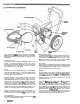
SETUP 1. Connect Hose and Gun (Refer to Fig 1.) NOTE: a. When tightening fittings at the pressure control, hold one wrench firmly on the hex of the pressure control fitting to keep it from rotating. Use another wrench to tighten the mating fitting. Remove the plastic cap plug from the filter outlet nipple and tightly screw the 15.2 m (50f t ) fluid hose onto the nipple. b. Tightly connect the whip hose between the fluid hose and the gun inlet connection. c.
OPERATION WARNING Pressure Relief Procedure To reduce the risk of serious bodily injury, including fluid injection, injury from splashing fluid or solvent in the eyes or on the skin, moving parts or electric shock, always follow this procedure whenever you shut off the sprayer, when checking or servicing any part of the spray system, when installing, cleaning or changing spray tips, and whenever you stop spraying. 1. 2. 3. 4. 5. Engage the gun safety latch. Turn the ON/OFF switch to OFF.
4. Cleaning a Clogged Tip WARNING To avoid a fluid injection injury, DO NOT hold your hand, body, or a rag in front of the spray tip when cleaning or checking a clogged tip. Always point the gun toward .the ground or into a waste container when checking to see if the tup IS clear. DO NOT try to "blow back" paint; this is NOT an air spray sprayer. a. Clean the front of the tip frequently during the day's operation. First, follow the Pressure Relief Procedure Warning on page 6.
FLUSHING GUIDELINES When t o Flush 1. New Sprayer. Your new UltraQ 400 Sprayer was factory tested in lightweight motor'oil which was left in to protect pump parts. Before using water-base paint, flush with mineral spirits, followed by soapy water, and then a clean water flush. Before using oil-base pain!, flush with mineral spirits only. 2. Changing Colors. Flush with*a compatible solvent such as mineral spirits or water. 3. Changing from water-base to oil-base paint.
TROUBLESHOOTING GUIDE WARNING - Pressure Relief Procedure To reduce the risk of serious .bodilv injury. including fluid injection, splashing fluid in i h e eyes or on the skin, or injury from moving parts or electric shock, always follow this procedure whenever you shut off the sprayer, when checkingor servicing any part of the spray system, when Installing, cleaning or changing spray tips, and whenever you stop spraying. 1. Engage the gun safety latch. 2. Turn the ON/OFF switch to OFF. 3.
TYPE OF PROBLEM ~~~~~~ WHAT TO CHECK If check Is OK, go t o next check WHAT TO DO Ifcheck is NOT OK refer t o this column MOTOR W O N 7 OPERATE Diagnosing circuit board indicator lamps. The normal condition is red lamp on, clear lamp on when board is telling pump to run. Follow Pressure Relief Procedure Warning. Remove gun from hose. Remove pressure control cover and check for faulty condition of circuit board lamps. Condition A both lamps on; pump won't operate and motor is not running I.
YPE OF PROBLEM Condition B (continued) WHAT TO CHECK f check is OK, go to next check i. Check microswitch 1306). With no fluid pressure in the pressure control disconnect wires TP18 and TP19. Check continuity across switch terminals with an ohmmeter. Switch contact should be closed. Depress actuator bunon. An audible "click" indicates the contacts have opened. Ohmmeter should read infinity. i. Check circuit board ( 3 4 0 1 by substituting with a good board. See page 22.
~~ TYPE OF PROBLEM WHAT TO CHECK If check is OK. go t o next check WHAT TO DO If check is NOT OK refer t o this column LOW OUTPUT 1. Check for worn spray tip. 1. Follow Pressure Relief Procedure Warning then replace tip. See your separate gun or tip manual. 2. Check t o see that pump does not continue to stroke when gun trigger is released. Plug in and turn on sprayer. Prime with paint. Trigger gun momentarily, then release and engage safety latch. Relieve pressure, turn off and unplug sprayer. 2.
TYPE OF PROBLEM NO OUTPUT (Continued) Ifcheck is , OK, go t o next check Check to see if intake valve ball and piston ball are seating properly. See manual 307-793. . Check displacement pump connecting . Replace pin if missing. Be sure retainer Check connecting rod assembly for damage. See page 25. !. Replace connecting rod assembly. See rod pin. See page 26. . Be sure crank in drive housing rotates; plug in sprayer and turn on momentarily to check. Turn off and unplug sprayer. See page 25.
TYPE OF PROBLEM WHAT TO CHECK If check is OK, go to next check WHAT TO DO If check Is NOT OK refer t o this column ELECTRICAL SHORT Buildino circuit breaker ooens as sooi as sprayer switch is turned on. CAUTION Any short in any part of thf motor power circuit, which i$ connected to the output sidc of the bridge, will cause thf bridge to burn out immediate ly.
~ SPIN TEST ~_____~ WARNING 1 Before doing this procedure, follow the Pressure Relief Procedure Warning o n page 17 to reduce the risk of a fluid injection injury, splashing fluids in the eyes or on the skin, injury from moving Darts. or electric shock. ~~~ ~~ For checking armature, motor winding and brush electrical continuity. Setup Remove the drive housing from the sprayer as described in Steps 1-9, page 25.
BRIDGE TEST Remove the bridge from the pressure control box and perform this test to determine if the bridge is functional. See Bridge Rectifier Replacement, page 20. Use a continuity tester, such as multi-meter set on the X1 ohms scale ( n ). Eight individual checks, or tests, must be performed. If the bridge fails even one test, it must be replaced. Fig 11 shows the position of the wires on the bridge.
GENERAL REPAIR NOTES WARNING Pressure Relief Procedure To'reduce the risk of serious bodily injury, including fluid injection, splashing fluid in the eyes or on the skin, or injury from moving parts or electric shock, always follow this procedure whenever you shut off the sprayer, when checking or servic: ing any part of the spray system, when installing, cleaning or changing spray tips, and whenever you stop spraying. 1 .Engage the gun safety latch. 2 .Turn the ONIOFF switch to OFF. 3 .
POWER SUPPLY CORD REPLACEMENT (See Fig 12 Et 131 WARNING follow the Pressure Relief Procedure Warning on page 17 to reduce the risk of a fluid injection injury, splashing in the eyes or on the skin, injury from moving parts, or electric shock. 1. Use the 19 mm open end wrench to remove the nut (337) from the filter stud (310). 2. Use the 13 mm socket wrench to remove the two screws (651 holding the pressure control to the frame. 3.
ON/OFF SWITCH REPLACEMENT (See Figs 14 Et 15) WARNING Before doing this procedure, follow the Pressure Relief Procedure Warning on page 17 to reduce the risk of a fluid injection injury, splashing in the eyes or on the skin, injury from moving parts, or electric shock. 1. Remove the pressure control cover and screws. 2. Remove the wires attached to the switch (302) at TPl and TP2, using a screwdriver. See page 2 2 , Fig 21. 3.
1 BRIDGE RECTIFIER REPLACEMENT (See Fig 161 WARNING Before doing this procedure, follow the Pressure Relief Procedure Warning on page 17 to reduce the risk of a fluid injection injury, splashing in the eyes or on the skin, injury from moving parts or electric shock. ~ ~~~ ~~ ~~ 1. Remove the pressure control cover and screws. 2. Disconnect all wires from the bridge ( 3 0 8 1 at the appropriate terminals. 3. Outside the pressure control box on the right side are two screws (331).
CHOKE REPLACEMENT (See Fig 17) 1. 2. Remove the pressure control cover and screws. Remove the grounding screw (312) and remove the lead. Loosen the appropriate screw on the terminal strip (336) and discornect the yellow/green choke lead. 3. Use the M8 wrench to remove the upper nut and lockwasher (337, U S ) on the outside of the pressure control box. 4. Remove the old choke (309) and install a new one in the reverse order of disassembly.
CIRCUIT BOARD REPLACEMENT (See Figs 20 8 21) r C l R C U l T BOARD WARNING r PRESSURECONTROL KNOB Before doing this procedure, follow the Pressure Relief Procedure Warning on page 17 to reduce the risk of a fluid injection injury, splashing in the eyes or on the skin, injury from moving parts, or electric shock. Be sure to unolua rhe soraverl 1. Remove the pressure control cover and screws. 2.
PRESSURE CONTROL REPLACEMENT the risk of a fluid injection injury, splashing in the 1. Disconnect the main fluid hose (72) and the secondary fluid hose, if used, from the sprayer. 2. Disconnect the fluid hose ( 2 3 ) from between the displacement pump outlet nipple (22) and pressure control inlet elbow (314). 3. Loosen the filter bracket nut ( 6 3 ) and washer (62) using a 19 mm open end wrench. 4. Hold the pressure control adapter (315) firmly with a 19 mm open end wrench.
~ ~~ STALL PRESSURE CALIBRATION I I W ARNlNG USE EXTREME CAUTION WHEN PERFORMING THIS CALIBRATION PROCEDURE to reduce the risk of a fluid injection injury or other serious bodily injury which can result from splashing, component rupture, electric shock, fire, explosion, or moving parts. NEVER attempt to increase the fluid outlet pressure by performing this calibration in any other way. NEVER EXCEED 192 bar (2750 psi) MAXIMUM WORKING PRESSURE.
r- CONNECTING ROD, DRIVE HOUSING, or CRANKSHAFT REPLACEMENT (See Fig 25) WARNING CAUTION DO NOT allow the gear cluster (26) to fall when removing the drive housing (6). It is easiiy damag- Before doing this procedure, follow the Pressure Relief Procedure Warning on page 17 to reduce the risk of a fluid injection injury, splashing in the eyes or on the skin, injury from moving parts or NOTE: ed if dropped.
19. Install the connecting rod (9). 20. Screw the displacement pump about 3/4 of the way into the bearing housing (6). Hold the pin ( 2 0 ) up to the pin hole in the connecting rod assembly (9) and continue screwing in the pump until the pin slides easily into the hole. Back off the pump until the top threads of the pump cylinder are flush with the face of the bearing housing and the outlet nipple ( 2 2 ) is facing back. Push the retaining spring (21)into the groove all the way around the connecting rod.
MOTOR BRUSH REPLACEMENT (See Figs 27 8 2 8 ) NOTE: New motor brushes are included with each Packing Repair Kit. Replace them when replacing the packings, and/or when they have been worn to a minimum of 9 / 1 6 on the longest side. 11. Reinstall the brush inspection covers, gaskets, and screws. Reinstall the motor shield and screws.
MOTOR CAPACITOR REPLACEMENT (See Figs 29 & 30) WARNING Relief Procedure Warning on page 17 to reduce the risk of a fluid injection injury, splashing in the eyes or on the skin, injury from moving parts or 1. Remove the control box cover (48). Disconnect the motor leads. 2. Remove the fan cover IF) and screws (G) from the rear of the motor. See Fig 29. 3. Use a screwdriver to gently lift the fan tab out of the motor shaft groove and remove the fan (El. 4.
1 MOTOR REPLACEMENT (See Fig 31 8 32) WARNING Before doing this procedure, follow the Pressure Relief Procedure Warning on page 17to reduce the risk of a fluid injection injury, splashmg in the eyes or on the skin, injury from moving parts, or electric shock. Be sure to unplug the sprayer! 1. Disconnect the pump outlet hose ( 2 3 ) from the displacement pump outlet nipple (22). 2. Remove the screws (51) and pressure control cover 3. (48)and disconnect the four motor leads.
13. Use a plastic mallet to gently tap the displacement pump (19)from the rear to loosen the drive housing (6)from the front end bell. Then pull the drive housing away from the front end bell. CAUTION ~ DO NOT allow the gear cluster (26) to fall when removing the drive housing (6). It is easily damaged if dropped. The cluster may stay engaged in either the front end bell or the drive housing.
PART DRAWINGS AND PARTS LISTS 307-671 31
PARTS DRAWING Model 230-963 Ultra" Includes items 1-112 11 400.
Includes items 1-112 REF PART NO. NO. 1 2 3 4 5 181-612 218-415 8 107-267 107-264 107-219 220-270 105-510 107445 9 11 13 218-359 218-363 107-209 14 19 180-192 220-647 x) 176-818 176-817 162-453 218-083 6 7 21 22 23 24 26 27 33 34 35 100-069 218-364 '178-934 218-361 104-008 107-212 39 40 102-932 218-353 41 42 065-099 106062 48 50 51 176884 101-242 104-811 218-326 179-936 1OE-075 52 155-665 53 214-no 43 44 45 QTY DESCRIPTION SHIELD, motor MOTOR, electric: 112 HP Includesitems 3.
Ref No. 40 PRESSURE C O N T R O L A S S E M B L Y Includes items 301 to 340 313 PARTS LIST REF PART NO. NO. DESCRIPTION 301 218-351 BARE PRESSURE CONTROL BOX Includes items 302 to 306 .ON/OFF SWITCH .BOOT, ONIOFF switch .GUARD, locking .MICROSWITCH BRIDGE, rectifier, SCR CHOKE FII TEE) , ..,. CORDSET, power supply; no plug SCREW, mach; slotted pan head; No.8 .....x. 5/16" . . .. CONNECTOR, conduit ELBOW. street; 1/4 n p t h x f l ADAPTER, 3/8 npttrn) x 1/4 nptlm) NIPPLE.
WIRING DIAGRAM THESE WIRES ARE CONNECTED TO TWO TERMINALS ON THE OTHER SIDE OF THE ONlOFF SWITCH SERVICE INFORMATION Listed below by the assembly changed are OLD and NEW parts. ASSEMBLY PART CHANGED STATUS Sprayer, Series OLD NEW OLD NEW OLD NEW OLD NEW OLD NEW OLD NEW REF PART NO. NO. NAME 14 218-618 Motor Cover 1 181-612 Motor Shield 16 217-593 Gun NOTE: This manual now includes complete service procedures. The parts list has new reference numbers.
ULTRA@ 400 TECHNICAL DATA Power Requirements Operating Range CyclesILiter (gallon) Power Cord Inlet Paint Strainer Outlet Paint Filter Pump Inlet Size Fluid Outlet Size Weight Wetted Parts Dimensions Delrin' and PTFE : 230 VAC, 50 Hz, 1 Phase, 3.7 AMP minimum : 0-192 bar (0-2750 psi) : 124 (470) : 2.5 mm 0 (13 ga.), 3 wire, 6 m (20 f t ) long : 16 mesh, 1190 micron, Stainless Steel Screen, reusable : 60 mesh, 250 micron, Stainless Steel screen, reusable : 314 npt w/30° I.D.