IMPORTANT SAFETY NOTICE Safe operation depends on reliable equipment and proper operating procedures. Performing the checks and services described in this manual will help to keep your Gradall Material Handler in reliable condition and use of the recommended operating procedures can help you avoid accidents. Because some procedures may be new to even the experienced operator we recommend that this manual be read, understood and followed by all who operate the unit.
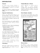
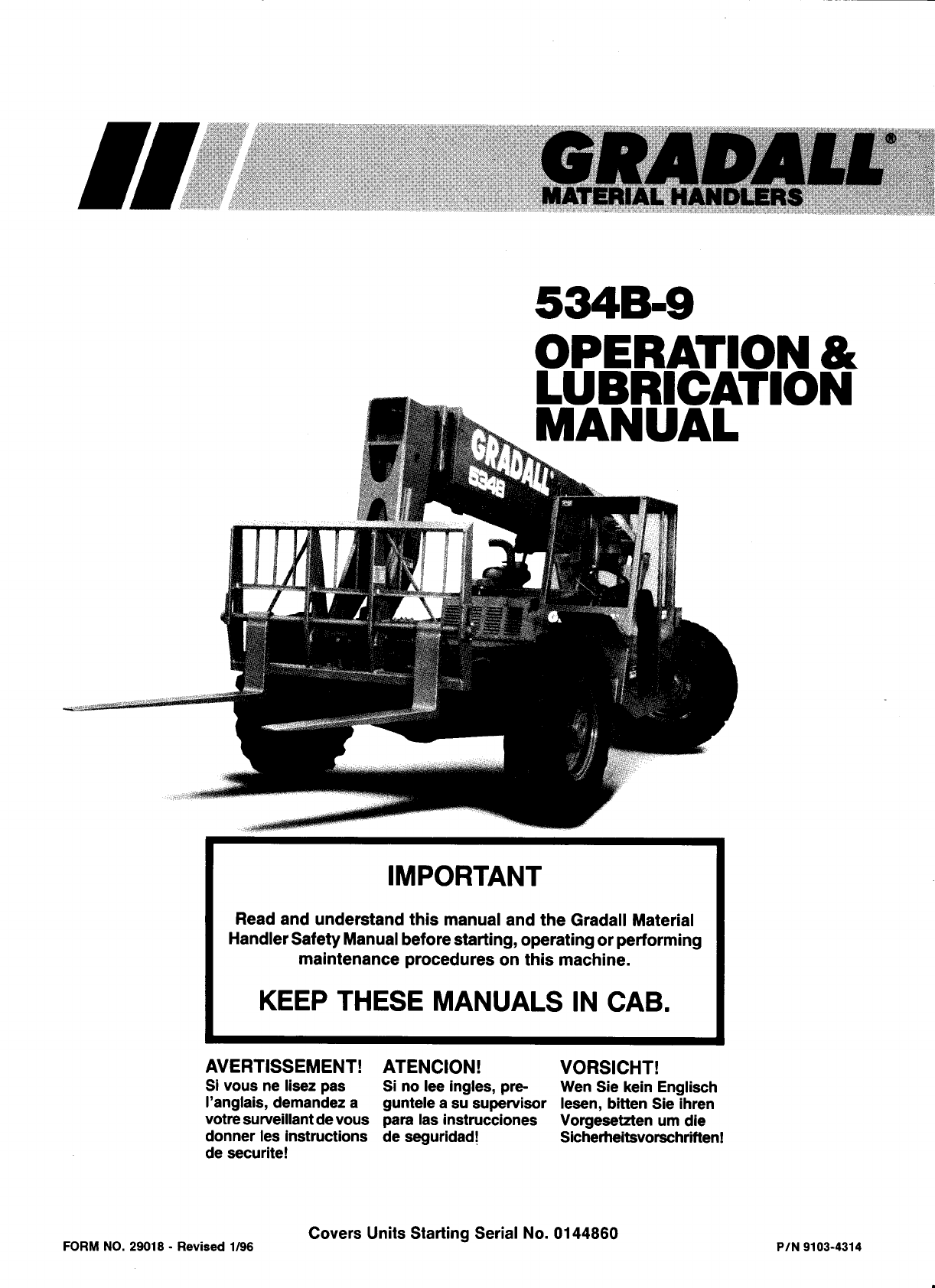
INTRODUCTION General Related Manuals & Decals The manual provides important information to familiarize you with safe operating procedures and operator maintenance requirements for the Gradall/ 534B-9 Material Handler. Separate publications are furnished with the material handler to provide information concerning safety, replacement parts, maintenance procedures, theory of operation and vendor components.
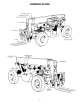
NOMENCLATURE 3
SAFETY HIGHLIGHTS Read and understand this manual, the Gradall Material Handler Safety Manual and all instructional decals and plates before starting, operating or performing maintenance procedures on this equipment. Operators of this equipment must have successfully completed a training program in the safe operation of this type of material handling equipment.
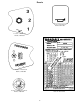
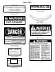
Decals 9103-3089 Located on Dashboard Part No.9103-3089 9100 -3039 Located on Dashboard Part No. 9100-3039 9100 -304 0 Located on Dashboard Part No. 9100-3040 Located on Right Cab Wall Part No.9103-3279 Located on Boom Lever Knob Part No.
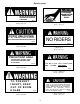
Decals (cont.) Located on Dashboard Part No. 9103-3341 Located on Left Cab Wall Part No. 9103-3396 FOR LONGER TURBOCHARGER L I F E , I D L E E N G I N E AT L E A S T I MINUTE AFTER START-UP AND BEFORE SHUT-DOWN. TO PREVENT ENGINE RING GEAR DAMAGE, WAIT 10 SECONDS AFTER ENGINE STOPS BEFORE ATTEMPTING TO RESTART. FOR OPTIMUM CONTROL AND BRAKE L I F E, U S L OW G E A R WH E N DESCENDING STEEP GRADES. Located on Dashboard Part No.
Decals (cont.) IMPORTANT HYDRAULIC OIL To prevent damage to the electrical system when using booster battery or charger, always connect (+) POSITIVE TO POSITIVE ( -) NEGATIVE TO NEGATIVE 7702-3006 Located on Hydraulic Reservoir Part No. 7702-3006 Located on Battery Cover Part No. 7702-3007 HOT EXHAUST Located on Boom Part No. 9100-3031 Located on Engine Cover Part No.
Decals (cont.) PRESSURIZEDCOOLINGSYSTEM REMOVE CAP SLOWLY DO NOT INSERT HAND IN OPENING WHILE ENGINE IS RUNNING 9103-3011 9104-3210 Located on Engine Cover Part No. 9103-3011 Located on Engine Cover Part No. 9104-3210 DO NOT USE OXYGEN USE “OIL PUMPED OR DRY NITROGEN.” CONSULT DEALER BEFORE CHARGING ACCUMULATOR NO RIDERS 9104-3206 9104-3211 Located on Accumulator Part No.9104-3206 Located at Cab Entrance & on Engine Cover Part No.
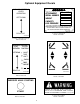
Optional Equipment Decals GRAD ALL GRADALL • AUXILIARY CONTROLS LEVER OPERATION 406 HILL AVE. S.W. NEW PHILADELPHIA. OHIO MADE IN U. S. A. ATTACHMENT SERIAL NUMBER WEIGHT CAPACITY HYD. PRESSURE LEFT/DOWN THE CAPACITY OF FORKLIFT. ATTACHMENT AND FORK COMBINATION MAY BE LESS THAN THE CAPACITY SHOWN ON ATTACHMENT - CONSULT FORKLIFT NAMEPLATE AND ALSO INSURE FORKS ARE OF PROPER SIZE. 9015-3001 RIGHT/UP Located on Attachment Part No. 9015-3001 9103-3417 Located on Instrument Console Part No.
OPERATOR’S CAB The standard cab is open on three sides and includes an overhead guard to provide protection from falling objects. variations in operator size. The adjustment release/lock lever is located beneath front edge of s e a t . We a r s e a t b e l t a t a l l t i m e s . An optional windshield wiper is available for use with enclose cabs. An ON/OFF control switch is l o c a t e d o n t h e w i p e r m o t o r. Never operate the handler unless the overhead guard is in place and in good condition.
Horn Button: Depress button to sound horn. Hourmeter: This meter indicates total time of engine operation in hours and tenths of hours. A brief description of controls and instruments is provided here as a convenience for the operator. These descriptions DO NOT provide complete operating instructions. Read and understand this manual and the FIEI Rough Terrain Forklift Safety Manual before operating the handler. Ignition Switch: This switch is actuated by a key.
CHECKS AND SERVICES B E F O R E S TA R T I N G E N G I N E (To be performed at beginning of each work shift) enter these ports, it can shorten the life of o-rings, seals, packings and bearings. Use extreme caution when checking items beyond your normal reach. Use an approved safety ladder. When adding fluids or changing filter elements, refer to the lubrication section of this manual to determine the proper type to be used.
ENGINE OPERATION NOTE: If engine is being started at beginning of work shift be sure to perform all “CHECKS AND SERVICES BEFORE STARTING ENGINE” (page 12). Starting Engine 1. Check to be sure that all controls are in neutral and that all electrical components (lights, heater, defroster, etc.) are turned off. Set parking brake. 2. Depress accelerator pedal approximately 1/4 to 1/3 o f travel from top. 3. Insert ignition key and turn clockwise to ON position. time while cranking engine. Repeat if necessary.
Stopping the Engine Operate engine at idle speed for a few minutes before turning it off. This allows engine coolant and lubricating oil to carry excessive heat away from critical engine areas. Allow engine to run at idle for a few minutes to allow the turbo components to cool. Turn key counterclockwise to stop position and remove key from ignition switch before leaving cab.
BRAKE SYSTEM General Service Brakes The brake system furnished on the handler includes a service brake and parking brake. The service brake is applied to the front wheels of the handler. Because service braking and “inching” (slow travel) functions overlap, some features of inching will be discussed here. Refer to Drive Train Section for additional information on inching travel. Oil for the brakes comes from the pilot circuit pump, thru an accumulator charging valve and the accumulator.
STEERING SYSTEM It is important that the operator practice maneuvering the handler in a safe, open area until he becomes thoroughly familiar with steering response and clearance required for tailswing and load when turning. Ninety degree rear wheel power steering is provided to reduce operator fatigue and to permit high maneuverability in close quarters. Be alert for any increase In effort needed to steer. If any difference is noted, notify maintenance personnel immediately for correction.
DRIVE TRAIN General Transmission The drive train provides two and four wheel drive includes the engine torque converter transmission drive shaft and front and rear driving axles. The transmission provides three speed ranges for both forward and reverse travel. Inching travel is directly related to drive train functions and will be discussed in this section.
Rear Driving Axle travel functions only in first and second gears. There i s n o h y d r a u l i c f l o w t o d r i v e m o t o r s i n t h i r d g e a r. The rear driving axle includes planetary hubs which are powered by hydraulic motors mounted on the inner face of the hubs. Hydraulic flow to drive motors is provided only in first and second gear speed ranges. Drive motors are free- floating in third gear. Inching travel is controlled by the service brake/inching travel pedal.
LEVELING THE HANDLER Leveling Handler Frame: Raising the boom (loaded or unloaded) when handler is leaning to the side can cause machine to tip over with little or no warning and cause serious injury or death. The handler is designed to permit tilting main frame eight degrees to left or right to compensate for uneven ground conditions. “LEVELING” means positioning the handler so that it is level from side to side (left to right with respect to a man sitting in operator ’s seat).
OPERATING PROCEDURES & TECHNIQUES This section highlights some common procedures discusses areas which may be new to even the experienced operator. With boom lowered below horizontal, forks can be removed from load by moving boom control lever forward and to the left until forks move rearward horizontally. Hydraulic Controls The closer the boom to horizontal, the less boom raise/lower movement required for inserting and removing forks.
Boom Extension Elevation: Numbers across bottom of sample chart (0' to 24') and numbers parallel to boom (1 to 5) represent boom reach as measured from front of tires to extended position. CAPACITY CHART: MODEL 534B-9 Number decals on boom (1,2,3,4 & 5) relate directly to boom extension. The largest number which can be read from operator’s seat indicates total boom extension and must be matched with boom angle to determine capacity. Boom extension relates to dimension “D” shown on serial number plate.
ATTACHMENTS Approved Attachments Carriage/Fork Capacities The standard carriage/fork capacity chart (located on the dashboard) indicates maximum reach and load capacities for handlers equipped with an approved carriage fork combination. These limitations apply to standard, approved carriage/fork combination except as stated on the capacity chart. Although the carriage/fork combination is most frequently used, several other Gradall-approved attachments are available for use with these material handlers.
Attachment Installation LOCK PIN (RAISED POSITION) RETAINER PIN RECESS QUICK SWITCH BOOM HEAD PIVOT 1. Retract quick switch (attachments tilt lever forward) to provide clearance. Check to be sure lock pin is secured in raised position with retainer pin. 2. Align boom head pivot with recess in attachment. 4. Engage quick switch (attachments tilt lever to rear). 5. Remove retainer pin and lower lock pin fully. 6. Secure lock pin in locked position using retainer pin. 3.
• • FORK POSITIONER LIGHT MATERIAL BUCKET PRECAUTIONS Always adjust fork position before engaging load. As with all other attachments, handler must be level before handling a load more than four feet above ground level (refer to page 19). PRECAUTIONS Handler must be level when handling a load more than four feet above ground level (refer to page 19).
2. Install light material bucket on boom head. mast combination. A separate capacity chart must be used for handlers equipped with mast. Study this chart carefully before attempting to handle a load with mast attachment. Observe all precautions and load capacity limits (listed previously) when handling loads with light material bucket. Do not attempt to handle a load with mast attachment until you have studied mast capacity chart carefully.
Procedure: SWING FORKS PRECAUTIONS l Read additional capacity information under Capacity heading. l Always level forks (horizontally) before swinging load to side. Swinging unleveled forks may result in load slipping from forks. l 1. Remove carriage/fork combination or other attachment from boom head (refer to Attachment Installation - page 23). 2. Install swing fork attachment on boom head. 3. Connect auxiliary hydraulic hoses to swing fork attachment.
SLOPE PILE CARRIAGE QUICK - SWITCH MOUNTED WINCH PRECAUTIONS PRECAUTIONS l Level handler before tilting carriage to l Maximum winch load capacity is reduced from normal carriage/fork load rating (refer to next heading - Capacity). engage load (refer to page 19). l Always level handler before lifting a load l Always level the handler before lifting a more than four feet above ground. load more than four feet above ground level (refer to page 19).
Controls: Capacity: Maximum lift capacity for the truss boom (with or without winch) is shown on serial number plate (located on right cab wall). However, maximum lift capacity applies only to certain areas within boom extension/elevation pattern of handler/truss boom combination. Refer to standard capacity chart. Study this chart carefully before attempting to handle a load with truss boom. A side load or a swinging load can cause the handler to tip over and/or damage the boom.
Procedure: chart carefully before attempting to handle a load with swing mast attachment. 1. Remove carriage/fork combination or other attachment from boom head (refer to attachment installation - page 23). NOTE: When swing mast is equipped with an optional panel handler attachment, additional restrictions in operation and capacity will apply. Refer to Swing Mast Capacity Chart or contact your Gradall Material Handler Distributor for complete instructions and restrictions on use. 2.
5. Inspect supporting surface at delivery point and have it leveled if necessary. 2. Install swing mast on boom head and connect auxiliary hydraulic hoses to swing mast diversion valve hoses. Also connect electrical cable at boom head. 6. Level handler before raising load. Observe all precautions and load capacity limits (listed previously) when handling load with swing mast. 7. If necessary, perform a “dry-run” (unloaded) of delivery to determine best position for handler. 3.
Recommended Lubricants & Capacities *Capacities are approximate - check level to be sure. **Hydraulic Fluid Specifications: ISO Grade 46, Pour Point F -20 to -40 SSU @ 100 F, 200-240 Flash Point, COC, F 280 min. Approved Supplier & Type: Union 46, Conoco Grade 46 or Citgo Grade 46 ***Approved Lubricants: Gradall Wet Brake Housing Fluid 1440-4535 or Mobil #424 ****Fill to Level Using Mixture of: 6 pints (2.8 Liters) Gradall Dif. Lube Additive 1440-4534 or Lubrizol #6178 34 pints (16.
LUBRICATION & MAINTENANCE DIAGRAM LUBRICANT SYMBOLS ATF - Automatic Transmission Fluid CG - Grease, Extreme Pressure DF - Diesel Fuel EO - Engine Oil GO - Multi Purpose Lubricant HF - Hydraulic Fluid MG - Extreme Pressure Moly Lubricant SL - Special Lube TF - Tractor Fluid SYMBOLS = Fitting = Other Service SEE MANUFACTURER’S COMPONENT LITERATURE FOR ADDITIONAL LUBRICATION AND MAINTENANCE INFORMATION Lubrication Notes l Clean filter housings using diesel fuel.
Item Daily (or 10 Hour) Lubrication & Maintenance (Service at whichever interval occurs first) Lube No. of Symbol Points 12. Air Cleaner Element Condition Indicator (check for clogged condition (red band showing) & clean or replace element as required) 14. Engine Crankcase Dipstick (check level & refill as required - item 13 is filler cap) 21. Transmission Dipstick (check level & replenish as required) 32.
Obtaining Hydraulic Oil Sample for Analysis 1. Operate unit until hydraulic oil reaches normal operating temperature. 5. Allow at least one pint of oil to flow into waste oil container to eliminate any contamination from hose. 2. Apply parking brake and observe hydraulic filter by-pass indicator with engine running at full throttle. Replace filter elements if necessary. 6. Move hose to CLEAN container to collect sample for analysis. 3.
MOVING HANDLER IN EMERGENCY NOTE: Early 534B-9 units were equipped with SOMA front drive axles and recent units are equipped with Rockwell front drive axles. Be sure to follow proper instructions for your unit. The following procedure assumes that handler cannot be moved under its own power. The safest way to move a disabled handler is to use a tow trucK of sufficient capacity to raise front wheels clear of ground - OR - use a ramp/flatbed vehicle of s u ff i c i e n t c a p a c i t y.
5. If handler is to be pushed, secure unit to pushing vehicle to prevent handler from rolling on its own with NO BRAKES. Pushing or towing handler with engine stopped, accumulator drained and parking brake released can be dangerous because there are NO BRAKES. Although manual steering is possible without power assist, STEERING WILL BE SLOW AND DIFFICULT. If handler is to be towed, use a rigid connection to prevent rear end collision with handler having NO BRAKES. PUSH OR TOW SLOWLY TO MAINTAIN CONTROL.
HAND SIGNALS Standard Signals - When handler work conditions require hand signals, they shall be provided or posted conspicuously for the use of both signalman and operator. No handler motions shall be made unless signals are clearly understood by both signalman and operator. Special Signals - When signals for auxiliary equipment functions or conditions not covered are required, they shall be agreed upon in advance by the operator and signalman.