IMPORTANT SAFETY NOTICE Safe operation depends on reliable equipment and proper operating procedures. Performing the checks and services described in this manual will help to keep your Gradall Material Handler in reliable condition and use of the recommended operating procedures can help you avoid accidents. Because some procedures may be new to even the experienced operator we recommend that this manual be read, understood and followed by all who operate the unit.
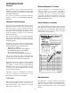
INTRODUCTION General Related Manuals & Decals The manual provides important information familiarize you with safe operating procedures and operator maintenance requirements for the Gradall/ 534-B Material Handler. Separate publication are furnished with the material handler to provide information concerning safety, replacement parte, maintenance procedures, theory of operation and vendor components.
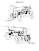
NOMENCLATURE 3
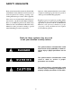
SAFETY HIGHLIGHTS Read and understand this manual, the Gradall Material Handler Safety Manual and all instructional decals and plates before starting, operating or performing maintenance procedures on this equipment. Operators of this equipment must have successfully completed a training program in the safe operation of this type of material handling equipment. Most safety notes included in this manual involve characteristics of the Model 534-B Material Handler.
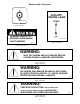
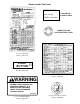
Decals Inside Cab Located on Dashboard Part No. 9100-3040 Located on Dashboard 9103-3310 Located on Dashboard Part No.9103-3089 Located on Dashboard Part No. 9100-3039 TO PREVENT ENGINE RING GEAR DAMAGE, WAIT 10 SECONDS AFTER ENGINE ROTATION STOPS BEFORE AT ATTEMPTING TO RESTART. DO NOT OPERATE MACHINE WITHOUT PROPER CAPACITY CHART IN PLACE Located on Dashboard Part No. 9103-3157 Located on Firewall Part No.
Decals Inside Cab (cont.) 9100-3041 Located on Dashboard Part No. 9100-3041 BRAKING CAPACITY IS REDUCED WHEN ENGINE IS NOT RUNNING. 9103-3244 Located on Dashboard Part No. 9103-3244 9103-3135 Located on Dashboard Part No. 9103-3135 WARNING: SHUT OFF ENGINE AND SET BRAKES BEFORE LEAVING GRADALL HANDLER UNATTENDED Located on Firewall Part No. 9100-3029 WARNING: ON GRADES AND UNEVEN GROUND PLACE FORKS IN CARRY POSITION (APPROX.
Decals Inside Cab (cont.) PARK BRAKE PARK BRAKE INSTRUCTIONS PULL TO SET PUSH TO RELEASE PARKING BRAKE LIGHT IDENTIFICATION START BUTTON 91043207 Located on Firewall Part No. 9103-3279 Located on Front Face of Dashboard Part NO. 9104-3207 Located on Manual Holder Part No. 9106-3031 WARNING DO NOT OPERATE THIS MACHINE WITHOUT FIRST READING THE OPERATOR’S MANUAL. IF A MANUAL IS NOT AVAILABLE, REFER TO AN AUTHORIZED GRADALL DEALER. 9103-3103 Located on Manual Holder Part No.
GFHGHGFH Decals Inside Cab (cont.) CAPACITY CHART: MODEL 5348-8 RATED CAPACITY 2 FT. LOAD CENTER DEATH OR INJURY MAY RESULT FROM CONTACTING ELECTRICAL LINES. UNLAWFUL TO PLACE ANY PART OF THIS MACHINE OR LOAD WITHIN 10 FEET OF HIGH VOLTAGE LINES OF UP TO 50,000 VOLTS. 9 FOR MINIMUM CLEARANCES OF HIGH VOLTAGE LINES IN EXCESS OF 50,000 VOLTS, SEE YOUR LOCAL STATE ANDFEDERAL REGULATIONS DO NOT DEFACE OR REMOVED THIS SIGN FROM THIS MACHINE Located on Mudguard Part No.
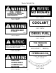
Decals Outside Cab NO RIDERS FUEL - DIESEL EXTINGUISH ALL OPEN FLAME AND SMOKING MATERIALS WHEN REFUELING. 9104-3211 Located on Hydraulic Reservoir & Left of Cab Door Part No. 9104-3211 9100-3052 Located on Fuel Tank Part No.9100-3052 COOLANT 9100-3032 Located on Radiator Part No. 9100-3032 DO NOT INSERT HAND IN OPENING WHILE ENGINE IS RUNNING DIESEL FUEL 9103-3011 Located on Radiator Part No 9103-3011 7702-3308 Located on Fuel Tank Part No.
Decals Outside Cab (cont.) DO NOT USE THIS MACHINE FOR LIFTING PERSONNEL. PINCH POINT AREA TO PREVENT INJURY, KEEP CLEAR ANYTIME MACHINE 9104-3209 IS RUNNING 9104-3215 Located on Mudguard Part No. 9104-3215 Located Below Boom Pivot Part No. 9104-3209 DO NOT USE BOOM AS WALKAWAY DO NOT STAND UNDER LOAD OR BOOM 9104-3217 9104-3216 Located on Boom Part No. 9104-3217 Located on Boom Part No.
HAND SIGNALS Standard Signals - When handler work conditions require hand signals, they shall be provided or posted conspicuously for the use of both signalman and operator. No handler motions shall be made unless signals are clearly understood by both signalman and operator. EMERGENCY STOP - With both arms extended laterally hands open downward, move arms back and forth. EXTEND TELESCOPIC BOOM With both hands clenched, point thumbs outward.
OPERATOR’S CAB The standard cab is open on three sides and includes an overhead guard to provide protection from falling objects. variations in operator size. The adjustment release/lock lever is located beneath front edge of seat belt at all times. An optional windshield wiper is available for use with enclosed cabs. An ON/OFF control switch is located on the wiper motor. Never operate the handler unless the overhead guard is in place and in good condition.
Engine Oil Pressure Gage: This gage displays engine oil pressure. Normal operating pressure is 35-50 psi (241-345 kPa). A brief description of controls and Instruments is provided here as a convenience for the operator. These descriptions DO NOT provide complete operating instructions. Read and understand this manual and the FIEI Rough Terrain Forklift Safety Manual before operating the handler. Forward/Reverse Lever: This lever engages forward or reverse travel.
CHECKS AND SERVICES BEFORE STARTING ENGINE (To be performed at beginning of each work shift) enter these ports, it can shorten the life of o-rings, seals, packings and bearings. Use extreme caution when checking items beyond your normal reach. Use an approved safety ladder. When adding fluids or changing filter elements, refer to the lubrication section of this manual to determine the proper type to be used. If spark arrestors are required, be sure they are in place and in good working order.
ENGINE OPERATION NOTE: If engine is being started at beginning of work shift be sure to perform all “CHECKS AND SERVICES BEFORE STARTING ENGINE” (page 6). Starting Engine 1. Check to be sure that all controls are in neutral and that all electrical components (lights, heater, defroster, etc.) are turned off. Set parking brake. button one time only before starting engine. If you use a different starting aid, be sure to follow manufacturer’s instructions carefully. Excessive ether may damage engine. 2.
Stopping the Engine cylinder walls and dilute lubricant in crankcase. Operate engine at idle speed for a few minutes before turning it off. This allows engine coolant and lubricating oil to carry excessive heat away from critical engine areas. To stop the engine, allow engine to run at idle for a few minutes, this is to allow the turbo components to cool. Turn key counter clockwise to stop position. Be sure to remove key from ignition switch before leaving cab.
BRAKE SYSTEM Service Brakes General The service brake is applied to the front wheels of the handler. The brake system furnished on the handler includes a service brake, inching brake and parking brake. Oil for the brakes comes from the pilot circuit pump, thru an accumulator charging valve and the accumulator. When the service/inching brake pedal is depressed far enough to actuate the brake valve, the hydraulic oil flows to the wet disc brakes in both front wheel hubs.
STEERING SYSTEM Ninety degree rear wheel power steering is provided to reduce operator fatigue and to permit high maneuverability in close quarters. It is important that the operator practice maneuvering the handler in a safe, open area until he becomes thoroughly familiar with steering response and clearance required for tailswing and load when turning. Be alert for any increase in eftort needed to steer. It any difference is noted, notify maintenance personnel immediately for correction.
DRIVE TRAIN General Transmission The drive train provides two and four wheel drive and includes the engine, torque converter transmission, drive shaft and front and rear driving axles. The transmission provides three speed ranges for both forward and reverse travel. Inching travel is directly related to drive train functions and will be discussed in this section.
Rear Driving Axle travel functions only in first and second gears. There is no hydraulic flow to drive motors in third gear. The rear driving axle includes planetary hubs which are powered by hydraulic motors mounted on the inner face of the hubs. HYdraulic flow to drive motors is provided only in first and second gear speed ranges. Drive motors are free-floating in third gear. Inching travel is controlled by the service brake/inching travel pedal. This pedal has three separate functions: 1.
MOVING HANDLER (Emergency Only) If handler must be moved, when the engine is not workable, extreme care should be used because: 1. With the engine not operating there will be NO steering. 2. With the wheel hubs adjusted to permit movement, ther will be NO brakes. If the handler is to be moved, do the following: 1. Place blocks on wheels to prevent movement. 2. On both rear axles, reverse the hub disengagement caps.** 3. Loosen front hub cover bolts equally until cover moves 3/16" to 1/4".
MATERIAL HANDLING Leveling To Level Handler: 1. Position machine in best location to lift or place load and apply brake. The handler is designed to permit tilting main frame eight degrees to left or right to compensate for uneven ground conditions. 2. Observe level indicator to determine whether machine must be leveled. Note position of indicator for later realignment. 3. If necessary, position boom in carry position and move carriage tilt machine level lever to left or right to level machine.
Attachments Although the carriage/fork combination is most frequently used, a number of other attachments available for use with the handler. 180ø and 100ø swing forks are available. A material bucket can be provided for light duty work. A truss boom is available to extend maximum reach and height and can be fitted with a winch when required. Consult your Gradall Material Handler Dealer for information on attachments designed to solve special material handling problems.
O P E R AT I N G P R O C E D U R E S & T E C H N I Q U E S This section highlights some common procedures and discusses areas which may be new to even the experienced operator. With boom raised above horizontal, forks can be removed from a load by moving boom control lever back and to the left until forks move rearward horizontally.
Rated Capacity Chart extension as measured from fully retracted position to extend position. These numbers do not reflect total boom length, only the number of feet of extension from fully retracted position. General Number decals on boom section number two (4,8, 12, 16 and 20) relate directIy to boom extension. The largest number which can be read from operator’s seat indicates total boom extension.
CAPACITY CHART: MODEL 534D-8 RATED CAPACITY 2 FT. LOAD CENTER USE WITH 9045-5007 48 CARRIAGE 9045-5008 66 CARRIAGE FOR OTHER ATTACHMENTS CONSULT FACTORY FOR LOAD RATING. USE LARGEST NUMBER VISIBLE FROM CAB TO DETERMINE BOOM EXTENSION. MATCH WITH BOOM ANGLE TO DETERMINE ALLOWABLE LOAD. BOOM EXTENSION IN FEET FROM TIRE TO LOAD CENTER (24 IN FRONT OF FORK FACE). FIGURES SHOWN ARE STACKING CAPACITY TRUCK LEVEL. RATED LIFTING CAPACITIES SHOWN ARE WITH MACHINE ON A FIRM. LEVEL SURFACE WITH UNDAMAGED.
Recommended Lubricants & Capacities Lubricantion Notes l Intervals shown are for normal (8 hour day) usage and conditions. Adjust intervals for abnormal usage and conditions. l Clean air filter and cleaner housing using diesel fuel. Dry components thoroughly using a lint free cloth. l Apply a light coating of engine oil to all linkage pivot points. l Check lubricant levels when lubricant is cool. l Drain engine and gear cases only after operation when lubricant is hot.
LUBRICATION & MAINTENANCE DIAGRAM 28
Suggested Lubrication & Maintenance Frequencies Hours . *#5 Boom Bearing Pads (extend boom fully and coat all wear paths on boom sections 2 and 3 with light coat of grease-retract and extend boom fully three times and wipe excess grease from bearings).
NOTES
NOTES
NOTES