1234567890123456789012345678901212345678901234567890123456789012123456789012345678901234567890121234567 1234567890123456789012345678901212345678901234567890123456789012123456789012345678901234567890121234567 1234567890123456789012345678901212345678901234567890123456789012123456789012345678901234567890121234567 1234567890123456789012345678901212345678901234567890123456789012123456789012345678901234567890121234567 123456789012345678901234567890121234567890123456789012345678901212345678901234567890123456789012
INTRODUCTION Related Manuals & Decals General The manual provides important information to familiarize you with safe operating procedures and operator maintenance requirements for the Gradall/ 544B Material Handler. Separate publications are furnished with the material handler to provide information concerning safety, replacement parte, maintenance components. Replacement manuals, decals and instruction plates can be ordered from your Gradall Material Handler Distributor.
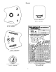
NOMENCLATURE 3
SAFETY HIGHLIGHTS Read and understand this manual, the Gradall Material Handler Safety Manual and all instructional decals and plates before starting, operating or performing maintenance procedures on this equipment. Operators of this equipment must have successfully completed a training program in the safe operation of this type of material handling equipment.
Decals 9103-3089 9100 Located on Dashboard Part No. 9103-3089 -3039 Located on Dashboard Part No.9100-3039 9100 -3040 Located on Dashboard Part No. 9100-3040 Located on Right Cab Wall Part No. 9104-3184 Located on Boom Lever Knob Part No.
Decals (cont.) Located on Dashboard Part No. 9103-3341 Located on Left Cab Wall Part No. 9103-3396 FOR LONGER TURBOCHARGER LIFE, IDLE ENGINE AT LEAST 1 MINUTE AFTER START-UP AND BEFORE SHUT DOWN. TO PREVENT ENGINE RING GEAR DAMAGE, WAIT 10 SECONDS AFTER ENGINE STOPS BEFORE ATTEMPTING TO RESTART. FOR OPTIMUM CONTROL AND BRAKE LIFE. USE LOW GEAR WHEN DESCENDING STEEP GRADES. Located on Dashboard Part No.
Decals (cont.) IMPORTANT HYDRAULIC OIL To prevent damage to the electrical system when using booster battery or charger, always connect ( + ) POSITIVE TO POSITIVE ( - ) NEGATIVE TO NEGATIVE Located on Hydraulic Tank Park No. 7702-3006 Located on Battery Cover Part No. 7702-3007 HOT EXHAUST Located on Side of Boom Part No. 9100-3031 Located on Engine Cover Part No.7734-3018 FUEL-DIESEL EXTINGUISH ALL OPEN FLAME AND SMOKING MATERIALS WHEN REFUELING Located on Fuel Tank Part No.
Decals (cont.) PRESSURIZEDCOOLING SYSTEM REMOVE CAP SLOWLY DO NOT INSERT HAND IN OPENING WHILE ENGINE IS RUNNING 9103-3011 9104-3210 Located on Engine Cover Part No. 9103-3011 Located on Engine Cover Part No. 9104-3210 DO NOT USE OXYGEN NO RIDERS USE “OIL PUMPED OR DRY NITROGEN.” CONSULT DEALER BEFORE CHARGING ACCUMULATOR 9104-3206 9104-3211 Located on Accumulator Part No. 9104-3206 Located at Cab Entrance & on Engine Cover Part No.
Optional Equipment Decals Located on Attachment Part No. 9015-3001 9103-3417 Located on Instrument Console Part No. 9103-3417 9103-3394 Located on Instrument Console Part No. 9103-3394 9102-3006 Located on Seat Pedestal Part No. 9102-3006 CHECK TO ASSURE QUICK SWITCH PIN IS FULLY ENGAGED AND LOCKED AFTER ATTACHMENT CHANGE. 2-9103-3023 Located on Boom Head Part No. 9103-3023 Located on Dashboard Part No.
OPERATOR’S CAB variations in operator size. The adjustment release/lock lever is located beneath front edge of seat. Wear set belt at all times. The standard cate is open on three sides and includes an overhead guard to provide protection from falling objects. An optional windshield wiper is available for use with enclosed cabs. An ON/OFF control switch is Located on the wiper motor. Never operate the handler unless the overhead guard is in place and in good condition.
Hourmeter: This meter indicates total time of engine operation in hours and tenths of hours. A brief description of control a and instruments provided here as a convenience for the operator. These descriptions DO NOT provide complete operating instructions. Read and understand this manual and the FIEI Rough Terrain Forklift Safety Manual before operating the handler. Ignition Switch: This switch is actuated by a key. In ON position (turned clockwise) voltage is available for all electrical functions.
CHECKS AND SERVICES BEFORE STARTING ENGINE (To be performed at beginning of each work shift) enter these ports, it can shorten the life of o-rings seals, packings and bearings. When adding fluids or changing filter elements, refer to the lubrication section of this manual to determine the proper type to be used. Use extreme caution when checking items beyond your normal reach. Use an approved safety ladder If spark arrestors are required, be sure they are in place and in good working order.
ENGINE OPERATION NOTE: If engine is being started at beginning of work shift be sure to perform all “CHECKS AND SERVICES BEFORE STARTING ENGINE” (page l2). Starting Engine 1. Check to be sure that all controls are in neutral and that all electrical components (lights, heater, defroster, etc.) are turned off. Set parking brake. NOTE: Engine will not start unless forward/reverse lever is in neutral. engine starts.
Stopping the Engine Operate engine at idle speed for a few minutes before turning it off. This allows engine coolant and lubricating oil to carry excessive heat away from critical engine areas. Allow engine to run at idle for a few minutes to allow the turbo components to cool. Turn key counterclockwise to stop position and remove key from ignition switch before leaving cab.
BRAKE SYSTEM General Service Brakes The brake system furnished on the handler includes a service brake and parking brake handler. The service brake is applied to the front wheels of the handler. Because service braking and “inching” (slow travel) functions overlap, some features of inching will be discussed here. Refer to Drive Train Section for additional information on inching travel. Oil for the brakes comes from the pilot circuit pump, thru an accumulator charging valve and the accumulator.
STEERING SYSTEM Ninety degree rear wheel power steering is provided to reduce operator fatigue and to permit high maneuverability in close quarters. It is important that operator practice maneuvering the handler in a safe, open area until he becomes thoroughly familiar with steering response and clearance required for tailswing and load when turning. Be alert for any Increase In effort needed to steer. If any difference Is noted, notify maintenance personnel immediately for correction.
DRIVE TRAIN General Transmission The drive train provides two and four wheel drive and includes the engine, torque converter, transmission, drive shaft and front and rear driving axles. The transmission provides three speed ranges for both forward and reverse travel. Inching travel is directly related to drive train functions and will be discussed in this section.
Rear Driving Axle travel functions only in first and second gears. There is no hydraulic flow to drive motors in third gear. Inching travel is controlled by the service brake/inching travel pedal. This pedal has three separate functions: The rear driving axle includes planetary hubs which are powered by hydraulic motors mounted on the inner face of the hubs. Hydraulic flow to drive motors is provided only in first and second gear speed ranges. Drive motors are free- floating in third gear. 1.
LEVELING THE HANDLER Leveling Handler Frame: Raising the boom (loaded or unloaded) when handler is leaning to the side can cause machine to tip over with little or no warning and cause serious injury or death. The handler is designed to permit tilting main frame eight degrees to left or right to compensate for uneven ground conditions. The rear axle pivots at the midpoint of the map frame to help assure that wheels will remain in contact with the ground.
O P E R AT I N G P R O C E D U R E S & T E C H N I Q U E S With boom lowered below horizontal, forks can be removed from a load by moving boom control lever forward and to the left until forks move rearward horizontally. This section highlights some common procedures and discusses areas which may be new to even the experienced operator. The closer the boom to horizontal, the less boom raise/lower movement required for inserting and removing forks.
Elevation: Boom Extension Numbers across bottom of sample chart (O’ to 40') and numbers parallel to boom (1 to 5) represent boom reach as measured from front of tires to extended position. Number decals on boom (1 thru 8) relate directly to boom extension. The largest number which can be read from operator s seat indicates total boom extension and must be matched with boom angle to determine capacity. Boom extension relates to dimension “D”shown on serial number plate.
ATTACHMENTS Approved Attachments Carriage/Fork Capacities Although the carriage/fork combination is most frequently used, several other Gradall-approved attachments are available for use with these material handlers. Contact your Gradall Material Handler Distributor for information on approved attachments designed to solve special material handling problems.
Attachment Installation 1. Retract quick switch (attachment tilt lever forward) to provide clearance. Check to be sure lock pin is secured in raised position with retainer pin. 2. Align boom head pivot with recess in attachment. 4. Engage quick switch (attachment tilt lever to rear). 3. Raise boom slightly to engage boom head pivot in recess. 5. Remove retainer pin and lower lock pin fully. 6. Secure lock pin in locked position using retainer pin.
l l FORK POSITIONER LIGHT MATERIAL BUCKET PRECAUTIONS PRECAUTIONS l Handler must be level when handling a Always adjust fork position before engaging load. load more than tour feet above ground level (refer to page 19). As with all other attachments handler must be level before handling a load more than four feet above ground level (refer to page 19). l Retract boom fully before loading bucket. Loading bucket with boom extended could damage structural members or extension cables.
2. Install light material bucket on boom head. mast combination. A separate capacity chart must be used for handlers equipped with mast. Study this chart carefully before attempting to handle a load with mast attachment. Observe all precautions and load capacity limits (listed previously) when handling loads with light material bucket. Do not attempt to handle a load with mast attachment until you have studied mast capacity chart carefully.
SWING FORKS Procedure: PRECAUTIONS 1. Remove carriage/fork combination or other attachment from boom head (refer to Attachment Installation - page 23). l Read additional capacity information under Capacity heading. l Always level forks (horizontally) before swinging load to side. Swinging unleveled forks may result in load slipping from forks. 2. Install swing fork attachment on boom head. l Because the swing forks can swing the 3. Connect auxiliary hydraulic hoses to swing fork attachment.
QUICK - SWITCH MOUNTED WINCH SLOPE PILE CARRIAGE PRECAUTIONS PRECAUTIONS l Level handler before tilting carriage to l Maximum winch load capacity is reduced engage load (refer to page 19). from normal carriage/fork load rating (refer to next heading - Capacity). l Always level handler before lifting a load l Always level the handler before lifting a more than four feet above ground. load more than four feet above ground level (refer to page 19).
Controls: Capacity: Maximum lift capacity for the truss boom (with or without winch) is shown on serial number plate (located on right cab wall). However, maximum lift capacity applies only to certain areas within boom extension/elevation pattern of handler/truss boom combination. Refer to standard capacity chart. Study this chart carefully before attempting to handle a load with truss boom. A side load or a swinging load can cause the handler to tip over and/or damage the boom.
Procedure: chart carefully before attempting to handle a load with swing mast attachment. 1. Remove carriage/fork combination or other attachment from boom head (refer to attachment installation - page 23). NOTE: When swing mast is equipped with an optional panel handler attachment, additional restrictions in operation and capacity will apply. Refer to Swing Mast Capacity Chart or contact your Gradall Material Handler Distributor for complete instructions and restrictions on use. 2.
2. Install swing mast on boom head and connect auxiliary hydraulic hoses to swing mast diversion valve hoses. Also connect electrical cable at boom head. 5. Inspect supporting surface at delivery point and have it leveled if necessary. 6. Level handler before raising load. Observe all precautions and load capacity limits (listed previously) when handling load with swing mast. 7. If necessary, perform a “dry-run” (unloaded) of delivery to determine best position for handler. 3.
Recommended Lubricants & Capacities *Capacities are approximate - check level to be sure. **Hydraulic Fluid Specifications: ISO Grade 46, Pour Point, °F-20 to -40 SSU @ 100°F, 200-240 Flash Point, COC, °F 280 min. Approved Supplier & Type: Union 46, Conoco Grade 46 ***Approved Lubricant Mobil 424 - (40 ounce bottle available under Gradall Part No. 1440-4535) ****Fill to level using a mixture of: Lubrizol #6178 - 6 pints (2.8 liters) - (32 ounce bottle available under Gradall Part No.
LUBRICATION & MAINTENANCE DIAGRAM SEE MANUFACTURER’S COMPONENT LITERATURE FOR ADDITIONAL LUBRCATION AND MAINTENANCE INFORMATION Lubrication Notes l Lubricate points indicated by dotted leaders on both sides of unit. l Clean filter housings using diesel fuel Dry componente thoroughly using a lint free cloth. l Intervals shown are for normal (8 hour day) usage and conditions. Adjust intervals for abnormal usage and conditions. l Check lubricant levels when lubricant is cool.
Item Daily (or 10 Hour) Lubrication & Maintenance (Service at whichever interval occurs first) 13. Air Cleaner Element Condition Indicator (check for clogged condition (red band showing) & clean or replace element as required) Lube Symbol - 1 17. Engine Crankcase Dipstick (check level & refill as required - item 18 is filler cap) EO 1 26. Transmission Dipstick (check level & replenish as required) ATF 1 37.
Obtaining Hydraulic Oil Sample for Analysis 1. Operate unit until hydraulic oil reaches normal operating temperature. 2. Apply parking brake and observe hydraulic filter by-pass indicator with engine running at full throttle. Replace filter elements if necessary. 3. Obtain a container to receive waste oil and a CLEAN container to receive oil sample. 5. Allow at least one pint of oil to flow in to waste oil container to eliminate any contamination from hose. 6.
MOVING HANDLER IN EMERGENCY NOTE: Early 544B units were equipped with SOMA front drive axles and recent units are equipped with Rockwell front drive axles. Be sure to follow proper instructions for your unit. The following procedure assumes that handler cannot be moved under its own power. The safest way to move a disabled handler is to use a follow of ground-OR-use a ramp/flatbed vehicle of sufficient capacity. For SOMA Axle Only The next safest is pushing the unit and least safe is towing the unit.
5. If handler is to be pushed, secure unit to pushing vehicle to prevent handler from rolling on its own with NO BRAKES. Pushing or towing handler with engine stopped, accumulator drained and parking brake released can be dangerous because there are NO BRAKES. If handler is to be towed, use a rigid connection to prevent rear end collision with handler having NO BRAKES. Although manual steering is possible without power assist, STEERING WILL BE SLOW AND DIFFICULT.
HAND SIGNALS Standard Signals - When handler work conditions require hand signals, they shall be provided or posted conspicuously for the use of both signalman and operator. No handler motions shall be made unless signals are clearly understood by both signalman and operator. Special Signals - When signals for auxiliary equipment functions or conditions not covered are required, they shall be agreed upon in advance by the operator and signalman.
Hydraulic Equipment 406 Mill Avenue, S.W. New Philadelphia, Ohio 44663 PHONE: (330) 339-2211 FAX: (330) 339-8468 WEB SITE: www.gradall.com CALIFORNIA Proposition 65 Warning Diesel engine exhaust and some of its constituents are known to the State of California to cause cancer, birth defects and other reproductive harm.