
User Manual

This section highlights some common procedures
and discusses areas which may be new to even the
experienced operator.
Hydraulic Controls
All boom and attachment movements are governed
by hydraulic controls. Rapid, jerky operation of
hydraulic controls will cause rapid, jerky movement
of the load. Such movements can cause the load to
shift or fall or may cause the machine to tip over.
Feathering
Feathering is a control operation technique used for
smooth load handling. To feather controls, move
control lever very slowly until load begins to move,
then gradually move lever further until load is
moving at desired speed. Gradually move lever
toward neutral as load approaches destination.
Continue to reduce load speed to bring load to a
smooth stop. Feathering effect can be increased by
lowering engine speed at beginning and near end of
load movement.
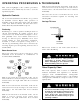
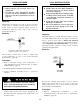
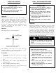
Boom Control lever
The boom control lever can be positioned to cause
individual boom movements or combinations of
boom movements as illustrated.
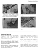
With boom raised above horizontal, forks can be
inserted under a load by moving boom control lever
forward and to the right until forks move forward
horizontally.
With boom lowered below horizontal, forks can be
removed from a load by moving boom control lever
back and to the left until forks move rearward
horizontally.
With boom raised above horizontal, forks, can be
under a load by moving boom control lever
back and to the right until forks move forward
horizontally.
OPERATING PROCEDURES & TECHNIQUES
With boom lowered below horizontal, forks can be
removed from a load by moving boom control lever
forward and to the left until forks move rearward
horizontally.
The closer the boom to horizontal, the less boom
raise/lower movement required for inserting and
removing forks.
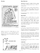
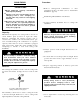
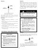
Carriage Tilt Lever
Move lever forward to tilt forks down and move
lever to rear to tilt forks up.
20
Always move boom to carry position
(horizontal or below) before leveling
frame. Attempting to level machine with
boom raised may cause it to tip over.
Rated Capacity Chart
All loads shown on rated capacity chart
are based on machine being on firm, level
ground; the forks being positioned evenly
on carriage; the load being centered on
forks; proper size tires being properly
inflated; and the handler being in good
operating condition.
The rated capacity chart, located on dashboard,
indicates maximum load capacities for handlers
equipped with Gradall-furnished carriage/fork
combination. These capacities apply to the standard
carriage/fork combinations except as stated on the
capacity chart.
CARRIAGE
TILT LEVER