
Installation Sheet
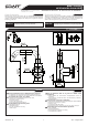

IOG 5049.30
3
This faucet complies with NSF61/9, ASME/ANSI A112.18.1
and CSA B 125 Standards.
Este grifo se encuentra conforme con losestandares de NSF61/9,
de ASME/ANSI A112.18.1 y de CSA B 125.
Installation Instructions Instrucciones de Instalación
1
ENGLISH
FAUCET INSTALLATION INSTALACIÓN DE LA GRIFERÍA
ESPANOL
~
LAVATORY FAUCET
GRIFO DE LAVATORIO
ENGLISH
~
ESPANOL
12
13
14
15
16
17
18
19
20
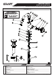
MOUNTING NUT
O-RING SEAL
O-RING SEAL
2,5MM HEX KEY
TUERCA DE MONTAJE
JUNTA TÓRICA
JUNTA TÓRICA
LLAVE ALLEN 2,5MM
A
Rev. 3 August 2018
HOLE PLUG
OBTURADOR
SPOUT BASE
BASE DEL CANO
O-RING SEAL
JUNTA TÓRICA
RUBBER WASHER
ARANDELA DE GOMA
METAL WASHER
ARANDELA DE METAL
HEX SOCKE CAP SCREW
TORNILLO CAP ASIENTO HEXAGONAL
B
C
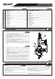
Position base seal (14) in underside cavity of the faucet base (20). Be
sure seal (14) is fully seated in groove.
Place faucet and center over hole of mounting surface .
From underneath the sink/bidet place rubber washer (16), metal
washer (19) on the stud bolt (9), then screw on the mounting nut
(12). Hand tighten only .
Make sure that the faucet is in proper position on the sink/bidet. Tighten
the mounting nut (12) using adjustable wrench.
Please check label on flexible supply hose for identyfication of hot (red
sticker) or cold (blue sticker) water.
Connect flexible hose (10) to the inlet valves of water supply lines. Be
sure to hold the flexible hoses in place when tightening the nut so as not
twist the hoses. Use adjustable wrench when tightening. Do not overti-
ghten.
1.
2.
3.
4.
5.
6.
Inserte la arandela de caucho (14) en el rebaje de la base de la mezcla-
dora (20). Asegúrese de que la arandela (14) quede al ras dentro del
rebaje.
Coloque el batería y centre en el agujero lateral de la superficie de
montaje .
Por debajo del lavabo/bidé coloque la arandela de goma (16), arandela
de metal (19) el tornillo (9), entonces atornille la tuerca de montaje
(12). Apriete únicamente a mano.
Asegúrese de que el batería se encuentra en la posición apropiada en el
lavabo/bidé. Ajuste la tuerca de montaje (12) usando la llave inglesa.
Verifique la etiqueta de la manguera flexible suministrada para identifi-
car si es agua caliente (etiqueta roja) o agua fría (etiqueta azul).
Conecte las manguera flexibles (10) a las líneas de fuente de entrada
de agua.
M ient ras fija s la tuerca, sujeta el tubo flexible para queno se tuerza.
Use la llave ajustable para ajustar las piezas. No ajuste demasiado.
1.
2.
3.
4.
5.
6.
SPECIAL KEY
LLAVE ESPECIAL
3MM HEX KEY
LLAVE ALLEN 3MM
1
20
MAX. 45mm
ø32
12
19
16
10
~
ESPANOL
See figs. 1 Ver. fig. 1
ENGLISH
2
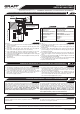
AFTER INSTALLATION BEFORE USE
DESPUES DE LA INSTALACIÓN Y ANTES DEL USO
Remove aerator insert (8) (use the special key (D) supllied) and
turn faucet handle to the full on mixed position.
Turn on hot and cold water supply valves and flush water lines for
15 seconds .
Check all connections at arrows for leaks. Re-tighten if necessary,
but do not overtighten.
Replace aerator insert (8).
IMPORTANT: This flushes away any debris that could cause
damage
1.
2.
3.
4.
1)
1)
Retire el inserto del aereador (8) (use una llave especial (D) anexa
al juego) y gire el mango del grifo a la posición de mezclado completo.
Abra las válvulas de suministro de agua fría y caliente y enjuague las
lineas de agua por 15 seg.
Chequee todas las conecciones para ver si hjay fuga de agua. Reaj
ste si es necesario, pero no ajuste demasiado.
Coloque el inserto del aereador (8).
IMPORTANTE: Esto limpia los residuos que podrían causar daño a
las piezas internas con un chorro de agua.
1.
2.
3.
4.
1)
1)
2
See figs. 2
Ver. fig. 2
14
10
11
FLEXIBLE HOSE 9/16-24
UNEF-M8X1-450
MANGUERA FLEXIBLE 9/16-24UNEF-M8X1-450
HEX SOCKE CAP SCREW
TORNILLO CAP ASIENTO HEXAGONAL
D
CUERPO DEL AEREADORAERATOR BODY
21
SPECIAL KEY FOR THE AERATOR
LLAVE ESPECIAL PARA EL AEREADOR
22
23
O-RING SEAL
JUNTA TÓRICA
SUPPLY TUBE
TUBO DE SUMINISTRO
9