
Installation Guide
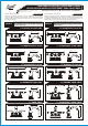
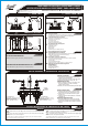
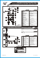
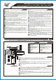
Table Of Contents

21 mm od brzegu p³yty
IOG 2017.00 CENTERSET (A3 F/F + A4 F/O)REV. 3
21 mm od brzegu p³yty
IOG 2017.00 CENTERSET (A3 F/F + A4 F/O)REV. 3
Coloque la placa de la base (9) en el grifo. Seguidamente coloque el
Slide undercover plate (9) on faucet. Next place faucet into position on
1)
1)
grifo en la posición adecuada en el lavatorio .
lavatory .
Compruebe aposición del grifo y asegure usando la tuerca (14). Ajuste
Check the faucet position and secure in place using the locknuts (14).
solo con la mano. No apriete demasiado.
Hand tighten only. Do not overtighten.
1) 1)
Si la superficie del lavatorio es desigual o la placa de la cubierta interior no esta
If sink is uneven or undercover plate does not properly seal, use of silicone sealant in
sellada correctamente, use el silicón en el lugar de la placa.
place of undercover plate may be required.
~
ESPANOL
ENGLISH
See fig.1 Vea fig.1
FAUCET INSTALLATION l INSTALACIÓN DEL GRIFO
2
1SET-UP DIAGRAM l DIAGRAMA DE INSTALACIÓN
LAVATORY
LAVATORIO
Entrada de agua caliente
Tuberia - 3/8” O.D. (9.5 mm)
Entrada de agua fría
Tuberia - 3/8” O.D. (9.5 mm)
COLD WATER INLET
Supply tube - 3/8" O.D. (9.5 mm)
HOT WATER INLET
Supply tube - 3/8" O.D. (9.5 mm)
4" (101.6mm)
REMOVE OLD FAUCET
Flush pipes thoroughly and turn off the water
supplies (hot and cold water).
Disconnect supply lines and remove old faucet.
Clean the sink surface of putty, dirt., etc.
BEFORE INSTALLING
Before installing the faucet, it is good to rinse
the supply pipelines in order to do away
with the dirty residues.
Besides, we recommend installing the filter taps.
QUITE EL GRIFO VIEJO
Limpie las tuberias a fondo y cierre las llaves
de suministro de agua (agua caliente y fría).
Desconecte las líneas de suministro y quite
el grifo viejo.
Limpie la superficie del fregadero de la masilla,
suciedad, etc.
ANTES DE LA INSTALACIÓN
Antes de instalar el grifo, es bueno enjuagar
las tuberías suministro para eliminar residuos.
Además, recomendamos el instalar los tapones
de filtro.
l
l
l
l
l
l
l
l
l
l
~
ESPANOL
ENGLISH
FLOW RATE INFORMATION
Max flow rate 2.2 gpm (8.3 l/min.) at 60 psi (4 bar).
INFORMACIÓN DE INTENSIDAD DE FLUJO
Flujo máximo 2.2 gpm (8.3 l/min.) con 60 psi (4 bar).
~
ESPANOL
ENGLISH
For easy installation of your GRAFF COLLECTION
faucet you will need:
to READ ALL the instructions completely before beginning,
to READ ALL the warnings, care and maintenance information.
To complete the project, you should:
gather the tools and all the parts you will need,
prepare the mounting area,
mount the faucet,
connect the supply lines,
finally test and flush the faucet.
You should have the following tools:
flat blade screwdriver,
adjustable wrench,
channel pliers,
®
Teflon tape,
plumbers putty or caulking (silicone).
Para la instalación fácil de su grifo de la
COLECCIÓN GRAFF usted necesitará:
LEER TODAS las instrucciones completamente antes de comenzar,
LEER TODA la información sobre las advertencias,
cuidado y mantenimiento.
Para terminar el proyecto, usted debe:
recolectar las herramientas y todas las piezas que usted necesitará,
prepare el área para el montaje,
monte el grifo,
conecte las líneas de fuente,
finalmente pruebe y limpie el grifo con un chorro de agua.
Usted debe tener las herramientas siguientes:
destornillador plano,
llave ajustable,
alicates acanalados,
®
cinta adhesiva de Teflon ,
masilla o silicona.
l
l
l
l
l
l
l
l
l
l
l
l
l
l
l
l
l
l
l
l
l
l
l
l
~
ESPANOL
ENGLISH
9.92" (252mm)
3.86" (98mm)
5.39" (137mm)
2.56" (65mm)
4.53" (115mm)
Model
Modelo
TOPAZ 1920-LM14
9.45" (240mm) 3.94” (100mm)
2.21" (56mm)
4.17" (106mm)
5.83" (148mm)
Model
Modelo
2020-LM11
TANGO 2720-LM27
Modelo
Model
7.32" (186mm)
5.39" (137mm)
7.40" (188mm)
1.38" (35mm)
2.24" (57mm)
min.2.76"-max.4.33"
min.2.09"-max.3.98"
min.70mm-max.110mm
min.53mm-max.101mm
5
6
.
x
a
m
-
5
3
.
n
i
m
0
0
0
0
Installation Instructions l Instrucciones de instalación
TWO HANDLE LAVATORY CENTERSET FAUCET
GRIFO DE DOS MANILLAS CENTERSET PARA LAVATORIO
This faucet complies with NSF61/9, ASME/ANSI A112.18.1
and CSA B 125 Standards.
Este grifo se encuentra conforme con losestandares de NSF61/9,
de ASME/ANSI A112.18.1 y de CSA B 125.
TM
IOG 2017.00
Rev. 4 April 20052
FIG. 2
TAPON DE DESAGÜE
COLLAR DEL DRENAJE
EMPAQUETADURA DE COLLAR
EMPAQUETADURA INFERIOR
ARANDELA
TUERCA ENSANCHADA
CUERPO DEL DRENAJE
PIPA DE DESCARGA
ASIENTO DEL PIVOTE
VARILLA DE BOLA
ASIENTO DEL PIVOTE
TUERCA DEL PIVOTE
PLATO DE AJUSTAMIENTO
BROCHE
TORNILLO
DRAIN PLUG
DRAIN COLLAR
COLLAR GASKET
UNDER-BOWL GASKET
WASHER
FLANGED NUT
DRAIN BODY
TAIL TUBE
BALL ROD SEAT
HORIZONTAL BALL ROD
BALL ROD SEAT
BALL ROD NUT
ADJUSTMENT PLATE
CLIP
SCREW
1
2
3
4
5
6
7
8
9
10
11
12
13
14
15
~
ESPANOL
ENGLISH
DRAIN ASSEMBLY INSTALLATION l INSTALACIÓN del DRENAJE
3a
Dismantle the drain assembly to the parts as shown (on fig. 2) with
the exception of under-bowl gasket (4), washer (5) and flanged nut (6).
Desmontar las piezas del drenaje según lo demostrado (en la fig. 2)
with the excepto la empaquetadura inferior (4), la arandela (5) y la tuerca
ensanchada (6).
ENGLISH
See fig. 2
~
ESPANOL
Vea fig. 2
LIFT ROD (fig.1 item 2)
VARILLA ELEWADORA (2 fig. 1)
1
2
3
4
7
8
9 10 11 12
14
15
13
5
6
FIG. 1
GRIFO
VARILLA ELEVADORA
ARANDELA
ADAPTADOR DEL ANILLO DIFUSOR
ANILLO DIFUSOR
MANILLA DERECHA
(agua fría)
MANILLA IZQUIERDA
(agua caliente)
CHAPA
BASE
PLACA DE LA BASE
CARTUCHO DERECHO
(derecha)
CARTUCHO IZQUIERDO
(izquierda)
EMPAQUETADURA DE ANILLO
CUERPO DEL GRIFO
TORNILLO
TUERCA
JUNTA DE CONO
TUERCA DEL ACOPLADOR
SPOUT
LIFT ROD
WASHER
AERATOR INSERT
BODY OF AERATOR
RIGHT HANDLE
(cold water)
LEFT HANDLE
(hot water)
HANDLE BASE
ESCUTCHEON
UNDERCOVER PLATE
RIGHT CARTRIDGE
(clockwise opening)
LEFT CARTRIDGE
(counterclockwise opening)
SEAL RING
FAUCET BODY
SCREW
LOCKNUT
CONE GASKET
COUPLING NUT
1
2
3
4
5
6a
6b
7
8
9
10a
10b
11
12
13
14
15
16
~
ESPANOL
ENGLISH
6b
10b
12
13
11
16
15
14
10a
9
8
7
1
2
6a
5
4
3
Installation Instructions l Instrucciones de instalación
TWO HANDLE LAVATORY CENTERSET FAUCET
GRIFO DE DOS MANILLAS CENTERSET PARA LAVATORIO
This faucet complies with NSF61/9, ASME/ANSI A112.18.1
and CSA B 125 Standards.
Este grifo se encuentra conforme con losestandares de NSF61/9,
de ASME/ANSI A112.18.1 y de CSA B 125.
TM
IOG 2017.00
Rev. 4 April 20053
4
MAKE CONNECTIONS TO WATER LINES l CONECCION A LAS FUENTES DE AGUA
Use mounting set to 3/8” copper tubes consisting of cone gaskets Use un completo de montaje para tuberias de Cu de 3/8” que
(15 fig.1) and coupling nuts (16 fig.1). consisten en empaquetaduras (15 fig.1) y uniones (16 fig. 1).
Use adjustable wrench when tightening. Do not overtighten. Utilice llaves ajustables cunado necesite ajustar alguna pieza. No
ajuste demasiado.
See fig. „Set-up Diagram”
Vea fig. „Diagrama de instalación”
~
ESPANOL
ENGLISH
Remove body of aerator (5), aerator insert (4) and washer (3) and
turn faucet lever handles all the way on. In case of faucet with cross
handles you should turn cross handles to the left (counterclockwise).
Open the hot and cold water supply valves and flush water lines for 15
1)
seconds .
Turn the hot and cold handles off.
Check all connections at arrows for leaks. Re-tighten if necessary, but
do not overtighten.
Next replace washer (3), aerator insert (4) and body of aerator (5).
Hand tighten only.
1)
1)
IMPORTANTE: Esto limpia las tuberias con un chorro de agua de todo residuo que podría
causar daño a las piezas internas.
CONGRATULATIONS! Your installation is now complete!
FELICIDADES Su instalación esta completa ahora!
Quite el cuerpo del aerador (5), el adaptador del aerador (4) y la
arandela (3) de la vuelta las manillas del grifo de tal manera que
este todo el tiempo abierto. En caso de grifo con manijas cruzadas
dé la vuelta a las manijas a la izquierda (contrario al reloj).
Abre las válvulas de agua caliente y fría y deje enjuagar las
1)
tuberias por 15 segundos
Cierre las manillas de agua fria y caliente.
Compruebe todas las conexiones para saber si hay fuga de agua.
Vuelva a apretar en caso de necesidad, pero no apriete demasiado.
Seguidamente substituya la arandela (3), el adaptador del aerador
(4) y cuerpo del aerador (5). Ajuste solamente con la mano.
IMPORTANT: This flushes away any debris that could cause damage to internal parts.
!
See fig. 1 Vea fig.1
5
AFTER INSTALLATION BEFORE USE l DESPUÉS DE LA INSTALACIÓN - ANTES DEL USO
~
ESPANOL
ENGLISH
Your Graff Collection faucet is designed and engineered in Su grifo de la colección Graff esta diseñado y dirigido acuerdo con
accordance with the highest quality and performance standards. Be los estándares de funcionamiento y calidad más altos. Este seguro
sure not to damage the finish during installation. Care should be no dañar las terminaciones del grifo durante la instalación. Cuide el
given to the cleaning of this product. Although its finish is extremely producto manteniendolo siempre limpio. Aunque su acabado es
durable, it can be damaged by harsh abrasives or polish. Never use extremadamente durable, puede ser dañado por los abrasivos o
abrasive cleaners, acids, solvents, etc. to clean any Graff pulientes ásperos. Nunca utilice limpiadores abrasivos,
Collection product. To clean, simply wipe gently with a damp ácidos, solventes, el etc. para limpiar cualquier producto de
cloth and blot dry with a soft towel. la colección de Graff. Para limpiar, simplemente use un
paño húmedo y seque con una toalla suave.
6
CARE AND MAINTENANCE l CUIDADO Y MANTENIMIENTO
~
ESPANOL
ENGLISH
Warranty conditions and warranty registration card are outlined Las condiciones de la garantía y la tarjeta del registro de la
on a separate sheet. garantía se encuentran en una pagina separada.
WARRANTY l GARANTIA
~
ESPANOL
ENGLISH
Installation Instructions l Instrucciones de instalación
TWO HANDLE LAVATORY CENTERSET FAUCET
GRIFO DE DOS MANILLAS CENTERSET PARA LAVATORIO
This faucet complies with NSF61/9, ASME/ANSI A112.18.1
and CSA B 125 Standards.
Este grifo se encuentra conforme con losestandares de NSF61/9,
de ASME/ANSI A112.18.1 y de CSA B 125.
TM
IOG 2017.00
Rev. 4 April 20055
IOG 2017.00
Rev. 4 April 20051
Installation Instructions l Instrucciones de instalación
TWO HANDLE LAVATORY CENTERSET FAUCET
GRIFO DE DOS MANILLAS CENTERSET PARA LAVATORIO
This faucet complies with NSF61/9, ASME/ANSI A112.18.1
and CSA B 125 Standards.
Este grifo se encuentra conforme con losestandares de NSF61/9,
de ASME/ANSI A112.18.1 y de CSA B 125.
TM
3.94" (100mm)
5.83" (148mm)
4.17" (106mm)
2.21" (56mm)
9.53" (242mm)
Model
Modelo
2020-LM12
Model
Modelo
CHANTEAUX 1120-LM15
9.84" (250mm)
4.76" (121mm)
2.21" (56mm)
2.99" (76mm)
3.66" (93mm)
Model
Modelo
ELEGANTÉ 1220-S2
Model
Modelo
CHANTEAUX 1120-S2
9.84" (250mm)
2.21" (56mm)
2.99" (76mm)
4.76" (121mm)
3.66" (93mm)
Model
Modelo
ELEGANTÉ 1220-S1
Model
Modelo
CHANTEAUX 1120-S1
9.84" (250mm)
3.07" (78mm)
2.21" (56mm)
4.25" (108mm)
1.65"
(42mm)
10.08" (256mm)
2.21" (56mm)
4.25" (108mm)
3.07" (78mm)
1.65”
(42mm)
Model
Modelo
ATLANTIS 1120-LM1
Model
Modelo
NANTUCKET 2520-LM15
2.21" (56mm)
5.16" (131mm)10.04" (255mm)
4.57" (116mm)
7.09" (180mm)
Dear Customer Estimado Cliente
Thank you for selecting our product. We are confident we can fully satisfy Muchas gracias por elegir nuestro producto. Estamos seguros que podemos
your expectations by offering you a wide range of technologically advanced satisfacer completamente sus expectativas ofreciéndole una amplia variedad
products which directly result from our many years of experience in faucet de productos tecnológicamente avanzados que resultan directamente de
and fitting production. muchos años de experiencia en grifos y su producción apropiada.
ENGLISH
~
ESPANOL
For care, use soft towel with soap and water only! Under no
circumstances should you use any chemicals. For faucets
with ORB(oil rubbed bronze) finish please be extra careful
not to damage, scuff or ruin the finish during the
installation and cleaning!
NOTE !!!
NOTA !!!
Para el cuidado, utilice solamente una toalla suave con jabón y aqua!
Bajo ninguna circunstancia no use productos químicos. Con los grifos
de acabado ORB (bronce frotado con aceite) hay que tener un cuidado
especial para no dañar, arañar o destruir el acabado durante su
instalación o limpieza!
9.84" (250mm)
3.07" (78mm)
2.21" (56mm)
4.25" (108mm)
1.65"
(42mm)
10.04" (255mm)
3.07" (78mm)
2.21" (56mm)
4.25" (108mm)
1.65"
(42mm)
Model
Modelo
ELEGANTÉ 1220-LM1
10.08" (256mm)
2.21" (56mm)
2.99" (76mm)
4.76" (121mm)
3.66" (93mm)
Model
Modelo
PESARO 1520-LM10
2.21" (56mm)
5.16" (131mm)9.96" (253mm)
4.57" (116mm)
7.09" (180mm)
21 mm od brzegu p³yty
IOG 2017.00 CENTERSET (A3 F/F + A4 F/O)REV. 3
IOG 2017.00
Rev. 4 April 20054
Entornille la tuerca (6), la arandela (5) y la empaquetadura inferior (4) lo
mas que sea posible.
Coloque la empaquetadura de collar (3) y el collar del drenaje (2) en el
agujero del lavatorio. Por debajo del lavatorio entornille el cuerpo del drenaje (7)
en el collar del drenaje (2). Posicione la empaquetadura de collar (3) y ajuste
manualmente el cuerpo del drenaje. Preste atención para alinear el cuerpo del
drenaje de modo que el agujero horizontal del cuerpo del drenaje esté en el
mismo plano que la varilla elevadora (elem. 2, fig.1).
Coloque la empaquetadura inferior (4) correctamente bajo el lavatorio y
entornille la tuerca ensanchada (6) firmemente pero no ajustando demasiado.
Coloque el tapón de desagüe (1) dentro del collar de drenaje (2), Posicione
el tapón de desagüe (1) de modo que el ojo del perno sea visible en el agujero del
cuerpo del drenaje (7).
Retire la broche (14) del varilla de bola (10); retire la tuerca del pivote
(12) del cuerpo, saque el asiento del pivote (11) de la tuerca y empuje la
tuerca atravez del varilla de bola (10) por el lado mas largofrom the longer
end con el hilo de rosca haciendo frente a una bola.
Inserte el varilla de bola (10) dentro del cuerpo del drenaje (7). Empuje la
varilla a través del ojo del perno del tapón de desagüe (1).
Ajuste la tuerca del pivote (12) asegurandose de que el asiento del pivote
(9 y 11) y la union de la bola estan correctamente instalados,
®
Aplique la cinta de Teflon en la pipa de descarga (8), y conectar al
cuerpo del drenaje (7).
Levante el tapón de desagüe (1) a la posición de abierto, moviendo el
varilla de bola (10) hacia abajo.
Insierte la varilla elevadora (elem. 2, fig.1) hacia abajo a travez del grifo
(elem. 1, fig.1) hasta la parte superior del plato de ajustamiento (13). Ajuste la
altura adecuada y ajuste el tornillo (15).
Elija la posición del varilla de bola (10) de uno de los agujeros del plato de
ajustamiento (13). Insrte el varilla de bola (10) atravez de la broche (14)
levante el plato de ajustamiento (13) y entonces la broche (14).
Pruebe si el tapón de desagüe (1) cierra el drenaje tirando de la varilla
elevadora. Si es que no cierra, vuelva a ajustar regulando el plato de ajustamiento
(13) y el varilla de bola (10).
Screw flanged nut (6), washer (5) and under-bowl gasket (4) down
as far as possible.
Insert collar gasket (3) and drain collar (2) into drain hole of a
lavatory. From underneath the lavatory screw drain body (7) onto drain
collar (2). Position collar gasket (3) and hand tighten drain body. Pay
attention to align the drain body so that the horizontal hole of drain body
will be in the same plane as a lift rod (2 fig.1).
Position under-bowl gasket (4) correctly under the lavatory and screw
flanged nut (6) firmly but do not overtighten.
Insert drain plug (1) into drain collar (2), position drain plug (1) so
that eye of bolt will be visible in outlet hole in drain body (7).
Remove clip (14) from horizontal ball rod (10); undo a ball rod nut
(12) from body, take out one ball rod seat (11) from a nut and push the nut
forward over horizontal ball rod (10) from the longer end with the thread
facing a ball.
Insert the horizontal ball (10) into a side hole of drain body (7). Push
the rod through the eye of the bolt of the drain plug (1).
Tighten ball rod nut (12) making sure that the ball rod seats (9 and 11)
and ball joint are properly installed.
®
Add Teflon tape to tail tube (8), and mount tail tube to drain body (7).
Lift the drain plug (1) to an open position, by lowering the horizontal
ball rod (10) down.
Insert lift rod (2 fig.1) down through spout (1 fig.1) and top of
adjustament plate (13). Adjust to proper height and tighten screw (15).
Choose the position of horizontal ball rod (10) in one of the holes in
adjustament plate (13). Insert horizontal ball rod (10) through one arm of
spring clip (14) and adjustament plate (13) and then second arm of spring
clip (14).
Try if a drain plug (1) closes the drain by pulling the lift rod. If not,
make corrections of position of adjustament plate (13) and horizontal ball
rod (10).
See fig. 2 Vea fig. 2
~
ESPANOL
ENGLISH
Installation Instructions l Instrucciones de instalación
TWO HANDLE LAVATORY CENTERSET FAUCET
GRIFO DE DOS MANILLAS CENTERSET PARA LAVATORIO
This faucet complies with NSF61/9, ASME/ANSI A112.18.1
and CSA B 125 Standards.
Este grifo se encuentra conforme con losestandares de NSF61/9,
de ASME/ANSI A112.18.1 y de CSA B 125.
TM
3b
AUTOMATIC DRAIN ASSEMBLY INSTALLATION l INSTALACIÓN DEL JUEGO DE DESAGÜE AUTOMATICO
Only in case of the TANGO 2720-LM27 model Sólo en caso de la modelo TANGO 2720-LM27 l
FIG. 2
Unscrew the nut (9) and remove the tailpiece (10) with washer (8) from the assembly.
Remove flanged nut (1) with under-bowl gasket (5) from drain collar (2).
Insert drain collar (2) with collar gasket (6), drain plug (3) and drain switch assembly (4) into
drain hole of a lavatory.
From underneath the lavatory thread the flanged nut (1) with under-bowl gasket (5) onto drain
collar (2). Hand tighten only.
Connect the tail piece (10) and the washer (8) with drain collar (2) by tightening the nut (9).
Insert trap nut and gasket onto tailpiece (10) and carefully slide trap over tailpiece.
Tighten trap nuts.
pipa de descagra
pipa de descagra
pipa de desca ga
pipa de desca ga
Desenroscar la tuerca (9) y quitar el (10) con la arandela (8) del conjunto.
Quitar la tuerca con brida (1) con la junta inferior (5) del anillo de desagüe (2).
Colocar el anillo de desagüe (2) con la junta del anillo (6), tapa protectora (3) y el juego de
alternador de desagüe (4) en el agujero de desagüe del lavabo.
Por la parte de abajo del lavabo colocar el tuerca con brida (1) con la junta inferior (5) en el anillo
de desagüe (2). Apretar únicamente a mano.
Conectar el (10) y la arandela (8) con el anillo de desagüe (2) ajustando la tuerca (9).
Colocar la tuerca del sifón y la junta sobre el (10) y con cuidado deslizar el sifón
sobre el .
Apretar las tuercas del sifón.
r
r
ENGLISH
~
ESPANOL
See fig. 2
Vea fig. 2
~
ESPANOL
ENGLISH
FLANGED NUT
DRAIN COLLAR
DRAIN PLUG
DRAIN SWITCH ASSEMBLY
UNDER-BOWL GASKET
COLLAR GASKET
WASHER
WASHER
NUT
TAILPIECE
TUERCA CON BRIDA
ANILLO DE DESAGÜE
TAPA PROTECTORA
JUEGO DE ALTERNADOR DE DESAGÜE
JUNTA INFERIOR
JUNTA SUPERIOR DEL ANILLO
ARANDELA
ARANDELA
TUERCA
PIPA DE DESCA GAR
1
2
3
4
5
6
7
8
9
10
6
10
9
1
5
4
8
2
7
3
min.0.98"-max.1.58"
(min.25mm-max.40mm)
Ø
Ø
1 1/4"
( 32mm)
Minimum hole in lavatory
Agujero mínimo en el lavabo
Ø Ø1.50"( 38mm)
Ø
Ø
2.36"
( 60mm)