
Installation Sheet

21 mm od brzegu p³yty
IOG 2040.65 TUB FILLER (10 STRON)
REV. 1
ENGLISH
For easy installation of your Para la instalación fácil de su grifo
GRAFF faucet you will need: de la GRAFF usted necesitará:
to READ ALL the instructions completely before beginning, LEER TODAS las instrucciones completamente antes de comenzar,
to READ ALL the warnings, care and maintenance information. LEER TODA la información sobre las advertencias,
To complete the project, you should: cuidado y mantenimiento.
gather the tools and all the parts you will need, Para terminar el proyecto, usted debe:
prepare the mounting area, recolectar las herramientas y todas las piezas que usted necesitará,
mount the faucet, prepare el área para el montaje,
connect the supply lines, monte el grifo,
finally test and flush the faucet. conecte las líneas de fuente,
You should have the following tools: finalmente pruebe y limpie el grifo con un chorro de agua.
adjustable wrench, Usted debe tener las herramientas siguientes:
channel pliers, llave ajustable,
®
Teflon tape, alicates acanalados,
®
plumbers putty or caulking (silicone). cinta adhesiva de Teflon ,
masilla o silicona.
l l
l l
l
l l
l l
l l
l l
l
l
l l
l l
l l
l
~
ESPANOL
IOG 2200.00
Rev. 1 April 2008
2
IOG 2200.00
Rev. 1 April 2008
1
Dear Customer Estimado Cliente
Thank you for selecting our product. We are confident we can fully satisfy Muchas gracias por elegir nuestro producto. Estamos seguros que podemos
satisfacer completamente sus expectativas ofreciéndole una amplia variedad
your expectations by offering you a wide range of technologically advanced
products which directly result from our many years of experience in faucet
de productos tecnológicamente avanzados que resultan directamente de
and fitting production.
muchos años de experiencia en grifos y su producción apropiada.
ENGLISH
~
ESPANOL
For care, use soft towel with soap and water only! Under no
circumstances should you use any chemicals.
ATTENTION!
ATENCIÓN!
Para el cuidado, utilice solamente una toalla suave con
jabón y aqua! Bajo ninguna circunstancia no use productos
químicos.
IMMERSION 2353-C9
Model
Modelo
Installation Instructions l Instrucciones de instalación
TUB FILLER
BATERÍA DE BAÑO
®
Installation Instructions l Instrucciones de instalación
TUB FILLER
BATERÍA DE BAÑO
®
Installation Instructions l Instrucciones de instalación
TUB FILLER
BATERÍA DE BAÑO
®
Installation Instructions l Instrucciones de instalación
TUB FILLER
BATERÍA DE BAÑO
®
Installation Instructions l Instrucciones de instalación
TUB FILLER
BATERÍA DE BAÑO
®
4) Screw the small terminal of the shower hose (P) into the exit of the 4) A la salida de la válvula conmutadora atornilla el fin pequeño de la
switch valve remembering to place a flat gasket. manguera de ducha (P), sin olvidar de meter una junta plana.
Use an adjustable spanner when tightening hose nuts. While tightening Al apretar las tuercas de las mangueras usa la llave inglesa. En el
hose nuts, hold the hoses with your hand so as not to let them twist. momento de apretar las tuercas de las mangueras, sostén las mangueras
en la mano para que no se tuercen.
5.2
4
OPERATING INSTRUCTIONS l LA DESCRIPCIÓN DEL FUNCIONAMIENTO
l l
l
l
Handles are used to open and regulate the water flow. Full flow is Para abrir la salida y la regulación del flujo del agua sirven las palancas.
obtained by turning the lever through 90° (the cold water handle on La apertura total sucede al tornar la palanca por el ángulo de 90° (de
the right goes clockwise, the hot water handle on the left acuerdo con el movimiento de las manillas del reloj en caso de la palanca
counterclockwise). The intensity of the water flow is regulated by del agua fría colocada en el lado derecho, en contrario del movimiento de
positions between 0°-90°. las manillas del reloj en caso de la palanca del agua caliente colocada en
Pressing the knob of the switch causes the water to flow out through el lado izquierdo). La regulación de la intensidad del flujo de agua sucede
the handshower, releasing the pressure causes it to flow through the en las posiciones 0°-90°.
tub spout. Apretar la bola de desviador causa la salida del agua por de la ducha de
mano, dejar de apretar la salida del agua por el grifo de bañera.
ENGLISH
~
ESPANOL
5
CARE AND MAINTENANCE l CUIDADO Y MANTENIMIENTO
Your Graff faucet is designed and engineered in accordance with the Su grifo de la Graff esta diseńado y dirigido acuerdo con los estándares de
highest quality and performance standards. Be sure not to damage the funcionamiento y calidad más altos. Este seguro no dańar las terminaciones
finish during installation. Care should be given to the cleaning of this del grifo durante la instalación. Cuide el producto manteniendolo siempre
product. Although its finish is extremely durable, it can be damaged by limpio. Aunque su acabado es extremadamente durable, puede ser dańado
harsh abrasives or polish. Never use abrasive cleaners, acids, por los abrasivos o pulientes ásperos. Nunca utilice limpiadores
solvents, etc. to clean any Graff product. To clean, simply wipe abrasivos, ácidos, solventes, el etc. para limpiar cualquier producto
gently with a damp cloth and blot dry with a soft towel. de la Graff. Para limpiar, simplemente use un pańo húmedo y seque
con una toalla suave.
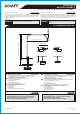
All dimensions and drawings are for reference only. For details, please refer to actual products.
Todas las dimensiones y dibujos sirven únicamente de referencia. Para consultar detalles, ver los productos.
MAX.~36-37/64” (~929mm)
MIN.~33-27/64” (~849mm)
1-31/32”
(50mm)
9-27/32” (250mm)
°
2
8
1-13/16" (46mm)
3-35/64" (90mm)
2-23/64"
(60mm)
2-41/64" (67mm)
ANTES DE LA INSTALACIÓN
Antes de instalar el grifo, es bueno ejuagar las tuberías
suministro para eliminar residuos.
Recomendamos el instalar los tapones de filtro.
l
l
BEFORE INSTALLING
Before installing the faucet, it is good to rinse the supply
pipelines in order to do away with the dirty residues.
We recommend installing the filter taps.
l
l
ENGLISH
~
ESPANOL
IMMERSION 2353-C9
ENGLISH
~
ESPANOL
~
ESPANOL
1
2
3
4
5A
5B
6
7
8
9
10A
10B
11
12
OR
3
4
1
2
OR
ENGLISH
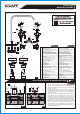
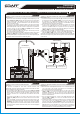
SPOUT INSTALLATION l MONTAJE DEL CAÑO
1
B
Finished floor
Acabado
de la pared
Cut
Corte
~1/4” (~6mm)
MAX. FINISHED FLOOR
MIN. FINISHED FLOOR
5
C
MIN. FINISHED FLOOR
SPOUT SET
MOUNTING RING
HEXAGONAL SCREW WITH A
SEATING (6 PIECES)
/TOGETHER WITH A 3/4”NPT
SPOUT CONNECTION ROUGH/
ROSETTE
HANDLE ASSEMBLY (right)
HANDLE ASSEMBLY (left)
VALVE EXTENSION
WASHER
FLANGED NUT
COUNTER NUT
RIGHT VALVE (with clockwise
opening cartridge)
LEFT VALVE (with
counterclockwise opening
cartridge)
HOSE 11-13/16” (300mm)
T-CONNECTION
O-RING SEALS
CAŃO JUEGO
ANILLO DE FIJACIÓN
TORNILLO CON ASIENTO DE 6
ÁNGULOS (6 PIEZAS)
/EN EL PAQUETE CON EL
CONJUNTO DE CONEXIÓN
CRUDA DEL CAÑO 3/4”NPT/
ROSETA
JUEGO DE MANILLA (derecha)
JUEGO DE MANILLA (izquierda)
EXTENSIÓN DE LA VÁLVULA
ARANDELA
TUERCA CON BRIDA
TUERCA DE CONTRA
VÁLVULA DERECHA (con
cartucho que se abre hacia la
derecha)
VÁLVULA IZQUIERDA (con
cartucho que se abre hacia la
izquierda)
MANGUERA 11-13/16” (300mm)
CONEXIÓN “T”
JUNTA O-RING
1
2.1 2.2
7
8
9
12
11 11
10B 10A
3/4NPT-14
3/4NPT-14
3/4NPT-14
6
5B
{
5A
{
On
Abierto
Off
Cerrado
¼ turn
¼ de vuelta
Counterclockwise opening
Se abre hacia la izquierda
On
Abierto
Off
Cerrado
Clockwise opening
Se abre hacia la derecha
¼ turn
¼ de vuelta
1) Cut the spout connection cover with a sharp knife (B)
approx. ¼" (6mm) above the finished flooring - see fig. 2.1.
2) Undo 6 screws (3) and remove the insert for the leakage
test (C) - fig. 2.2.
3) Replace the insert (C) with the spout (1). Pay attention if
o-rings (OR) are properly placed in the spout adapter
grooves; if necessary lubricate the seals (OR) with
silicone lubricant.
4) Position the mounting ring (2) against the spout connection
rough (A) so that the mounting holes in the ring and
module were in axis with one another fig. 3.1. Fix the ring to
the rough with the screws (3). Before tightening up the
screws (3) make sure that the spout (1) is placed properly.
5) Remove the protective foil from the spout (1). Slightly
dampen the place where the rosette (4) touches the spout
and the part of the spout below the rosette with water and
soap. Gradually pull the rosette (4) down, to the floor level -
fig. 3.2. Clean the spout (1) with a soft cloth and remove the
remaining water and soap.
1) Corte con un cuchillo afilado la protección del conjunto de
conexión del caño (B) en la altura más o menos de ¼"
(6mm) sobre el nivel del suelo - mire el dibujo 2.1.
2) Destornille 6 tornillos (3) y desmonte el elemento para la
prueba de hermeticidad (C) - dib. 2.2.
3) En el lugar del elemento (C) meta el caño (1). Fíjese en la
posición adecuada de juntas o-ring (OR) en las ranuras
del adaptador del caño, si lo considera necesario antes del
montaje lubrifique levemente las juntas (OR) con el
lubricante de silicona.
4) Coloque el anillo de fijación (2) en relación con el conjunto
de conexión cruda del caño (A) así que los huecos de
montaje en el anillo y en el conjunto de conexión del caño se
encuentren en el mismo eje - dib. 3.1. Sujete el anillo del
conjunto de conexión del caño con los tornillos (3). Antes de
apretar los tornillos (3) asegúrese que el caño (1) se
encuentra en la posición adecuada.
5) Quite la lámina de protección del caño (1). Moje levemente
con agua y jabón el lugar de unión entre la junta de la roseta
(4) y el caño, ya también la parte del caño que se encuentra
por debajo de la roseta. Vaya bajando la roseta (4) hasta
conseguir el nivel del suelo - dib.3.2. Limpie el caño (1) con
un trapo suave y quite los restos del agua y jabón.
MIN. FINISHED FLOOR
4
A
OR
MIN. FINISHED FLOOR
4
1
3
2
A
3.1
4.1
4.4
4.5
4.2 4.3
3.2
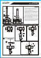
HANDLES INSTALLATION l INSTALACIÓN DE LAS MANILLAS
2
6
7
8
IOG 2200.00
Rev. 1 April 2008
6
IOG 2200.00
Rev. 1 April 2008
5
IOG 2200.00
Rev. 1 April 2008
4
IOG 2200.00
Rev. 1 April 2008
3
ENGLISH
~
ESPANOL
4.6 4.7
HANDLE BASE EDGE
BORDE DE LA BASE
DE LA MANILLA
HANDLE EDGE
BORDE DE LA MANILLA
5.2
8
9
10B
c
l
o
a
c
h
k
c
r
w
e
s
e
i
l
a
e
d
5.2
5.1
5.1
8
HANDLE BASE EDGE
BORDE DE LA BASE
DE LA MANILLA
HANDLE BASE EDGE
BORDE DE LA BASE
DE LA MANILLA
BATH EDGE
BORDE DE LA BAÑERA
BATH EDGE
BORDE DE LA BAÑERA
5.1
5.1
Next turn hande to OFF position
(max. clockwise direction - LEFT handle
max. counterclockwise direction - RIGHT handle)
Luego girar la manilla en la posición OFF
(al máximo hacia la derecha - la palanca IZQUIERDA
al máximo hacia la izquierda - la palanca DERECHA)
See fig. 4.1-4.5 Vea fig. 4.1-4.5
1. Insert valve extension (6) into the hole of a deck. From underneath 1. Meta la extensión de la válvula (6) en el agujero en la cubierta. Por
the bath place the washer (7) and then screw the flanged nut (8) – debajo de la bañera inserte la arandela (7) y enrosque la tuerca con
fig.4.1. brida (8) – fig.4.1.
2. Thread the counter nut (9) onto the valve (10B) as show fig. 4.2. 2. En la válvula (10B) enrosque la tuerca de contra (9) de acuerdo con
3. From underneath the bath thread the valve (10B) to the valve la fig. 4.2.
extension (6) until the whole spline of the cartridge (A) protrudes 3. Por debajo de la bañera inserte la válvula (10B) a la extensión de la
from the hole see fig. 4.3. válvula (6) hasta que aparezca toda la polichaveta del cabezal (A) de
4. Put the handle assembly (5B) onto the spline (A), then holding the acuerdo con la fig. 4.3.
handle base (5.1), screw the handle assembly onto the thread of the 4. Inserte el juego de la manilla (5B) sobre la polichaveta del cabezal (A),
cartridge until the resistance is felt (fig. 4.4). y luego sujetando la base de la manilla (5.1) enrosque el juego de la
5. To eliminate the distance (H) turn the valve (10B) counterclockwise manilla sobre la rosca del cabezal hasta sentir la resistencia (fig. 4.4).
until the handle base (5.1) reaches the deck (fig.4.5). 5. Para eliminar la distancia (H) gire la válvula (10B) hacia la izquierda
hasta el momento en el que la base de la manilla (5.1) se apoye en la
superficie del bañera (fig.4.5).
Adjustment of position of handle assembly (5B) Regulación de la ubicación del juego de la manilla (10B)
A. Adjustment of position of handle base (5.1) fig. 4.6: A. Regulación de la ubicación de la base de la manilla (5.1) fig. 4.6:
1. Loosen up the flanged nut (8). 1. Afloje (desenrosque ligeramente) la tuerca con brida (8).
2. From underneath the bath turn the valve extension (6) in such way 2. Por debajo de la bañera gire la extensión de la válvula (6) para lograr
that, the longer edge of the base (5.1) lies in parallel to the deck edge que el borde mas largo de la base de la manilla (5.1) esté paralela al
as on fig. 4.6. borde del bañera de acuerdo con la fig. 4.6.
3. Tighten back the flanged nut (8). 3. Ajuste la tuerca con brida (8) hasta sentir resistencia.
B. Adjustment of handle position (5.2) fig. 4.7: B. Regulación de la ubicación de la manilla (5.2) fig. 4.7:
1. Turn the handle (5.2) fully clockwise to the OFF position (RIGHT 1. Gire la manilla (5.2) al máximo hacia la derecha hasta llegar a la
handle – max. counterclockwise direction). posición OFF (la palanca DERECHA – al máximo hacia la izquierda).
2. Turn the valve (10B) clockwise until the edge of the handle (5.2) lies 2. Gire la válvula (10B) hacia la derecha hasta el momento en el cual el
in parallel to the handle base edge (5.1). borde de la manilla (5.2) esté paralela al borde de la base de la manilla
3. Tighten back the flanged nut (8). (5.1).
3. Ajuste la tuerca de contra (8) hasta sentir resistencia.
Repeat steps for second valve.
Repita los pasos con la segunda válvula.
~
ESPANOL
~
ESPANOL
ENGLISH
ENGLISH
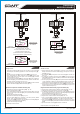
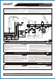
CONNECTING TO THE WATER SUPPLY l CONEXIÓN A LA INSTALACIÓN ALIMENTADORA
3.1
CONNECTING TO THE WATER SUPPLY l CONEXIÓN A LA INSTALACIÓN ALIMENTADORA
3.2
VERSION 1: TUB FILLER WITHOUT SHOWER DIVERTER VARIANTE 1: BATERÍA DE BAÑOS SIN CONMUTADOR DE DUCHA
See fig. 1 & 5.1 Mire los dib. 1 y 5.1
1. Connect one end of the feeding hoses (Z) (available separately) to the 1. Conecte las mangueras alimentadoras (Z) (accesibles por separado)
valves (11A) and (11B) and the other end to the ferrules of the water por un lado a las válvulas (11A) y (11B), y por el otro al tubo corto de
supply system valves. Pay attention that the hot and cold water is las válvulas de la instalación alimentadora. Tenga en cuenta la
correctly connected. It is recommended to mount ball valves with a conexión correcta del agua fría y caliente. Es recomendable montar
filter on the water supply. válvulas de bola con filtro en la alimentación.
2. The ferrule of the system supplying water to the spout connection 2. El tubo corto de la instalación que alimenta el conjunto de conexión
rough (A) should be equipped with a water supply pipe with a 3/4”NPT cruda del caño (A) debería poseer una tubuladura con la rosca
male thread placed in the wall at such a height that it is possible to exterior de 3/4”NPT situada en la pared a la altura que facilite la
correctly connect the valves (11A) and (11B) with the installed conexión correcta a través de las mangueras (12) con las válvulas
T-connection (13) using the hoses (12). (11A) y (11B) con el tubo en T (13) instalado.
3. Screw the T-connection (13) onto the nipple. Avoid using too much 3. Atornille el tubo en T (13) en el racor. No lo haga forzando al apretar.
force while tightening the connection. 4. Una las mangueras (12) por un lado a las salidas laterales de las
4. Connect one end of the hoses (12) to the lateral outputs of the valves válvulas (11A) y (11B), y por el otro al tubo en T instalado (13).
(11A) and (11B) and the other to the installed T-connection (13). Al apretar las tuercas de las mangueras use la llave inglesa. Al apretar las
Use an adjustable spanner to tighten the hose nuts. While tightening the tuercas de las mangueras, guarde las mangueras con la mano para que
nuts, hold the hoses in the hand to avoid twisting them. no se tuercen.
VERSION 2: TUB FILLER WITH SHOWER DIVERTER VARIANTE 2: BATERÍA DE BAÑOS CON CONMUTADOR DE DUCHA
See fig. 5.2 Mira el dib. 5.2
The tub filler is adapted to work with a shower diverter (with La batería de baños está adaptada al trabajo con el conmutador de ducha
showerhead). When the shower diverter and the showerhead have been (con el auricular). Tras montar correctamente el conmutador y el
correctly installed on the edge of the bath: auricular de ducha en el borde de la bañera:
1. Connect feeding hoses (Z) on one side to valves (11A) and (11B) 1. Une las mangueras de alimentación (Z) por un lado a las válvulas
and on the other side to the stub pipes belonging to the supply system (11A) y (11B), y por el otro a los tubos cortos de las válvulas en la
valves. Make sure that the hot and cold water supplies have been instalación alimentadora. Ten en cuenta la conexión adecuada del
correctly connected. It is recommended to install ball valves with agua fría y caliente. Se recomienda el montaje de válvulas de bola con
a filter. el filtro en la alimentación.
2. Connect the hoses (12) on one side to side entries of the valves 2. Une las mangueras (12) por un lado a las salidas laterales de las
(11A) and (11B) and on the other side to side entries of the switch válvulas (11A) y (11B), por el otro a las entradas laterales de la
valve. válvula conmutadora.
3. Using a hose (D), connect the central exit of the switch valve to the 3. La salida central de la válvula conmutadora une por la manguera (D)
stub pipe of the system which feeds the spout connection rough (A). con el tobo corto de la instalación que alimenta el conjunto de
Attention: The inbuilt stub pipe of the spout connection supply conexión cruda del caño (A). Atención: El tubo corto situado en la
system (A) should have a terminal with 3/4”NPT external thread. If pared de la instalación que alimenta el conjunto de conexión del caño
the tub filler works with the shower diverter, the T-connection (13) is (A) debería tener una tubuladura con la rosca exterior 3/4”NPT. El
not required. paquete que consta de conexión “T” (13) en caso de colaboración de
la batería de baños con el conmutador de ducha no es necesario.
5.1
max. 1-1/2”
(max. 38mm)
MIN. FINISHED FLOOR
A
Floor finishing layer
Capa de acabado del suelo
3/4”NPT
12 12
D
12 12
12
11B
11A
Edge of the bath
Borde de la bañera
Cold water inlet
Entrada de agua fría
Hot water inlet
Entrada de agua caliente
D
13
3/4”NPT
13
MIN. FINISHED FLOOR
A
Edge of the bath
Borde de la bañera
Floor finishing layer
Capa de acabado del suelo
Cold water inlet
Entrada de agua fría
Hot water inlet
Entrada de agua caliente
max. 1-1/2”
(max. 38mm)
3/4”NPT
3/4”NPT
3/4”NPT 3/4”NPT
Z Z
11B
11A
ENGLISH
~
ESPANOL
ENGLISH
~
ESPANOL
WARRANTY l GARANTÍA
Warranty conditions and warranty registration card are outlined on a Las condiciones de la garantía y la tarjeta del registro de la garantía se
separate sheet. encuentran en una pagina separada.
A
5.1
5B
{
10B
c
o
a
d
u
n
r
i
t
e
u
e
c
r
i
o
z
l
q
w
l
k
a
c
e
i
s
H
5B
{
6
7
8
10B
9
Installation Instructions l Instrucciones de instalación
TUB FILLER
BATERÍA DE BAÑO