ffiRAFTjFEN 2-1/4 x 3-1/4 RB Series 8 Service & Parts Manual
1/4 x 3 1/4 RB SERHS 8 GRAFLEX with REVOLVING BACK TABLE OF CONTENTS SERVICE INSTRUCTIONS Front Door TOp DOor Front Plate Body Parts Bellows Ground Glass Ektalite Field Lens Hood Idler Frame Mirror Frame Release Focal Plane Shutter Disassembly Clean and Lubricate Reassemble, Adjust, Time Revolving Back Attaching Back Slide Lock or Retaining Strip Velvet - Revolving Frame Wood Spacer Strips Revolving Ring Revolving Latch Back Parts Catalog Front Door Top Door Front Plate Body Parts Bellows Ground Glas
2E X 3± R® a. Section 20A Page 1 Sel`ies 8 GRAFLEX EE2QiE2Pg± !p±p_Ppp± , Front Plate £p_ecial P±eQa_a_t±ons _f_Q±r=: -(.. 1. Front Door i Panel h Spring fu Replacement fu Brace fu Cover`ing ji± Removal iL 2. covering Top Door. h Handle i Catch 3. Front Plate h Adjustment i Pinion Replacement 1. EiQp__t Door___(#_7_?=Z2± fl lhe fl.ont door. (#777) is secured by three #0 x i" oval head wood scl`ews (#15280-4). :§s:::i::::£§e::::w:::::ode:;a::::::g:i:::=:::k:§§::£::o::£:§C:i:;i.
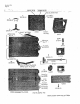
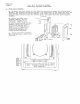
Section 20A Page 2 ;.a + .-.., ; A,r. j~rfeEL--=itH r3EEEGLttH fR!ffDIVo%fy:rr2:pav^ L J55TLr±3l= •.J±2JiL-_-€] 9055 .'giv 15183-8 1- I 5 9 6 FRONT PLATE COMPLETE NQ.
Section `20A 2± x 3i R. 8. Series 8 GRAFLEX POP DOOR, Page 3 FR0hTT QT¥. l`f.: . . \.3. 10 CAICH - TOP DOOR 150814 15082-4. Scl'ew - Front plate to body Screw - Top door strap to body Screw - Front door to body 15085-10 15180-3 15280-4. 15281-4228 Screw - Top door catch to body Screw - Focusing I`od bear.ing to Hinge - Body section of top door 717 FRONT DOOR A5SE},BH 15282-4 6 8 Door -front Spring -fl.ant door 346 g::8:i;gf= °=:o:€°:oof 7329 30172-P20 2409 i.10 5.01 4. 2.02 _RT.
Section 20A 2± x 3i R. 8. Series 8 GRAFLEJ£ . Page 4 Front Door., 3. _TQp_ ___D__oQ__I=`„ FI`ont Plate Front Plate (#13659). I.emove the focusing knob #||Zg8?:n:E: (#||428) , the f::a::::tr3Ea5:iri:gwi#lii85? focusing rod bearing (#1142°) 9rE:: ?gen::::!.:;:n:: :::8:;P378* g .±±:tc£::Eaw.:38 ±::.:+sthe front bellows frame sol.ew must be removed. from the camera bottom to free the bc)lstel. block, and remove th.e front plate..complete. (#13659) ±seisi;s[#;g;55:o::dp:::e ;;±=~;+ri/d;"{#ii536}`iovL[L.
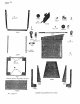
Section 208 . Page 1 2± x 3i R. 8. Series 8 GRAFux Body Parts ipg.cial pre£Lautions for: .---- f. i. 2. Bellows Ground Glass and Ektalite Field Lens 3. Hood 4. 5. 6. i Idler. Frame Mirrol' Frame Release Bello-ws (#7752). i Remove thef font panel. Remove four #2-56 x i" oval head screws (10482-4.). At the bottom of the rear. bellc>ws fl`ame, I'emove two #2 x i" I'ound head screws (#15182-4.). At the top partition plate, loosen the three round head scl`ews and slide the bellows down and out.
Section 208 Page 2 3,'= . -`-. :--::=::-::::::-I:=__::---i:--::::::I--:: - 10645: .15ae+aj, '. !N:.E2F2T68\, •.-Ni'i,,6±H3T€! `t52--.- Z.-8.i -i--:::--*-i:iiir---rfe_:i----:_--_--:ir_-:::-iif-:::-:---_-: EffiHH -r3_.OJ_50; .- EEi E= • '2i_2! !l_!.T`.a_T±! 0126: : 7 7 5_2J !~ ( `Li2.I ti §1- a 2 =_41 Jar§J Ll.
Section 208 Page 3 2± x 3E R. 8. Series a GRAFIEX BODY PARTS Qty. 50 Catch - hood 10482-4 Screw - lens flange to front plate 122 126 Foot, Camera -forward Pin - Name .plate to body 150-2-8 Screw Screw Screw Screw Screvi 15082-4. 151824 15182~4. 15281-4 232 24.8 - Inside angle block - tripod nut to c ase - rear bellows frame to body ~ inside pal`tition plate - bottom plate to body Plate -mirl.
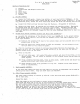
Section 208 Page 4 - © - !1 lT6`5 i 15o .80-51, i 2 2 § -6 0 L== ta15.2 81 -`4, 'T •10 0 -2-4 ©£ .2285 2 24o7i tar" ck.I •1' 52 81 -4 i-35TB o =3 L~ •f-a:ir 245' -TAPE ; No.11504 .`',"-Tfl!j:iap, a 255: G-ROUND CLASS ASSEMBLY N5.13017' .€_2_9 5 [I,l!,il ,;,; !2?i&9® •.I 0,6 4 5 . a-- ,L5J±2_-4J :"BRDR FRA"E.COMPLETE No.
Section 208 Page 5 2+- x 3f R. 8. Series 8 GRAFIIEjt GROUND GRASS, ELI.iAsh, hREOR FRch4E '=.ty' -If..-. Unit cost List 13ol7 2g36 Field Lens - Ektalite 14.278 REhASL IEvjiR - iflRROR FRch{E 228o3 (Order 2 of #11504-) Tape -scl`een edge 3188l-P3 :::Z8 (Use screirs #113 i #15181-4) i g:=: : g::::: :::::nscreen 11504. (Use screw #15281-4) i;:::8:I::::::::::::Se lever plate ::;::-;:lF::::;:::i!:t::;::e §§§§ 24.07 24.2C loo-2-4 205 263 34.
Section 208 Page 6 2+ x 3± R. 8. Sel'ies 8 GRAFI.FX Body Parts i_ ___ng±r_rQr ____F_ra_fpe fu (#?2_8_Q3±. a. Mirl.or (#229 5i#5!5|::;::::ment h Frame.spring fr Frame complete (#22803) replacement Hil`ror (#2295) replacement. .. (i) |t will be convenient to I.emove the hook::gn8L9::Erg:i:;.::r=:; (£i±85a::8:::h 2 and 3. Set focal plane ctirtain open. clip.-Remove two mirl'or Clip screws from 6ther .clip; I`.emov§ this clip, and then remove the mirror. (2).
Section 20C Page 1 2± x 3± R. 8. Series 8 GRAELEX Focal Plane Shutter SDecial Precautions for: i. i. Disassembly jit Shutter setting plate h Tension setting plate jL Curtain and Rollers 2. Clean and Lubricate 3. Reassemble, Adjust, Time Disassemfty. oval head screws (#15283-8). Shutter setting plate (#12724.) is secured by f our #3 x „" long. NOTE: Screw in forward top plate hole is cut off to.3/ g The illustration does not show the outside f.
Section 20C Page 2 1-g155,, Hit ffi a_06 163---pZ I 3- 0 I 3 „*3-a ; LEVER : iNo.
Section 20C 2± x 3± R. a. Series a GRAFLEX Page 3 FOCAL PLANE SRTTTER Qty. i.`.- 24.18 24.21 12724. GEAR R0I.LEE AS5EREI;Y CURTAIN ASSREI,Y SHUTTER PIAIE com>IEIE Unit cost List 2.50 4.25 7.50 .05 .07 .05 j!i;i i§:#€:::i¥i::::::i:i:::Sse lever 30663-P2 Pin - winding key a focuging kdob 14.231 TENsloN PLATE COMPLETE :::2g 14.251 15081-3 15BO-4 15283-8 152j33-8 153 221 267 2431 6551 17077 .10 .10 .45 :;:::; :e;::::::i;:I::se pawl rEh'si oi¢ ROLhiR Assrfu.BI,I 260 24.07 4.
Section 20C Page 4 2± x 3± R. 8. Series 8 GRAFLEX . Focal Plane Shutter i+___Reass_epple,__fld.iust+I__E±_PL§. fu The axis of the roller must be cemented squarely to the. lop.gitud.inal di-.men.sion of the curtain. Failul.e to do this will cause the curtain to. roll to one side .and:bind against the camera body. I.ecementing. Remove rc>llers from .the camera to .b.e assul.ed .of th.e best..alignment when a Lubricate curtain roller beari.ngs and replac; assembly. . .
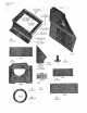
Section 20D 2¥ x 3± R. a. Series a GRAFIEX Page 1 Biv_p lvi n g _ _P_e=j2¥ Special PI.ecautions for: Attaching Back to Camera -~, Sliding Lock or Retainer Stl`ip Velvet ( Wood Spacer Strip Revolving Back Ring Revolving Back Ijatch li___ ___Attach±_pg___Back to Camera. Ihe revolving back (#24.25) is attached to the Camera body with eight #1 x ±`' flat head wood scl`ews from the back and three #1 x i" oval head wood sol.ews from the side. LS|i di ng _I Qcl€ . _ i.{._#? 7J..
Section 20D Page 2 . ~, _ . _ ,--..- ; ?H3•.... ® ;L:2i! ¥.[l_50-a--i3] i i.,ji-zTffl¥: •!£-E'6-9; :FTBAfaLEAs~s_EinBL7NQ-fo66Oj * ;±i3l`:. + t ..a. .i_5ZLj2t4 __---.----.--.--'.~,,.a~r.+:...:..,.`.;..`,...._.<`..-.!E£~CK`.C.gee,.E±E.IE.¥.?..24?i.5.I.-i_:.::...._~,..w....`.::.i....:i.,.
Section 20D Page 3 2¥ x 3± R. 8. Series a GRAFIEX REV0IjvING BACK Qty. 24.2 5 REVo|,i.riNG BACK CoMPRETE 27 119 Lock -sliding Screw - ring to I`evolving frame :g:::i (Order attaching screws) (Use scl'ew #15182-4) §::e¥ =L:::a±::Ego:::::i:: Wood 258 Ring -I.
i !,
• Section 20E Page 1 2Tf x 3± R. 8. Seri-es 8 GRAFLEX . r.T\TX=K SCRLtws PARI FiNISH NURERE USE RBQUIRLD Per. ' SIZE NEI Pm25 Total Assem STANDARD loo-24 SC^ELWS S-8 Hirl-or frame to rod ¥„ #2-56FT .2'0 10482-4. Lens flange to` front plate a" #2-56OH .20 15080-3 Mil`ror fl.ame bearing plate to body 1 3/16„ #O FH .20 15081-3 Wo.od spacer strip to revolving fl`ame 7 3/16" #1 rH .2D Geal` roller light shield. 15081-4.
Section 20E Page 2 2± x 3+ R. 8. Series 8 GRAFLH STCCK SCREWS PART NET IiunebR FI N I SH RE QUI RD USE Per SIZE PER 25 Total Assem SPECIAL SCELWS Ground glass fra.me to body -front hill-I'or. lever release arm to plate A:irl`or clip to mirror frame 118 Shuttel' release lever to plate Ring to revolving fl.ame S.
-. i. _ _I -__: e= i-.' '` -__+ .---. I_ - - -I T=_- :__ _ L `,-.
GRAFI.EX, IHc. Main Offices and Factories: Rochester 8, N® Y„ U. So A® Eastern Service Offices: 50 Roe.kefeller Plaza, Suite 922 New York 20, N.Y.