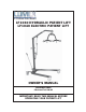
A Graham-Field Brand LF1030 HYDRAULIC PATIENT LIFT LF1040 ELECTRIC PATIENT LIFT OWNER'S MANUAL CD001030-1040 ©Graham-Field 10/03 IMPORTANT: READ THIS MANUAL BEFORE OPERATING YOUR PATIENT LIFT
CONTENTS INTRODUCTION ................................................................................................................... 4 SPECIAL NOTES ................................................................................................................. 5 SAFETY PRECAUTIONS ..................................................................................................... 6 FEATURES ..............................................................................................................
INTRODUCTION Congratulations on your purchase of a Lumex patient lift. The following pages will provide you with important safety and operating instructions on the use of patient lifts, slings, and accessories, as well as maintenance and warranty information. Read this manual carefully before operating your patient lift and refer to it as often as needed.
SPECIAL NOTES Warning: Do not operate this equipment without first reading and understanding this manual. If you are unable to understand the warnings, cautions and instructions, contact your dealer or a healthcare professional before attempting to use this equipment. Failure to do so may result in serious injury or damage to your patient lift. MAINTENANCE Maintenance MUST be performed by qualified personnel ONLY.
SAFETY PRECAUTIONS IMPORTANT: Before using patient lift, please read and adhere to the following safety precautions and warnings. Failure to do so could result in serious injury or damage to your patient lift. Always consult your healthcare professional to determine safe methods most suitable for your individual abilities. Protect yourself, your attendant and patient lift by having it serviced regularly.
Warning: Unauthorized modification of your patient lift or the use of non-Lumex replacement parts may change the structure of the lift and could create a hazardous condition, which may result in serious injury and will void the warranty. Warning: LF1030 Hydraulic Patient Lift only: The hydraulic pump is sealed at the factory. If service is required, the unit must be returned to the factory for repair.
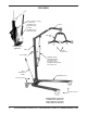
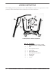
FEATURES Battery, battery charger, & control box (LF1040 electric patient lift only) Boom Actuator (LF1040 electric patient lift only) Spreader bar LF1040 electric patient lift Mast 6-point suspension Push handle Hydraulic pump (LF1030 hydraulic patient lift only) See above left for LF1040 electric patient lift components Base adjustment handle Adjustable base Locking casters Swivel casters LF1030 hydraulic patient lift LF1040 electric patient lift (unless otherwise specified, callout applies to
HANDLING PROCEDURES SHIPPING AND TRANSPORTATION INSTRUCTIONS If the patient lift is to be reshipped by common carrier, it should be packed in the same carton/s in which it was received (the LF1030 is shipped in one carton; the LF1040 motor may be packaged separately from the frame). Unpacking 1. Check for any obvious damage to the carton or its contents. If damage is evident, notify the carrier or your authorized Lumex Dealer. 2. Remove all loose packing from the carton. 3.
ASSEMBLY INSTRUCTIONS The LF1030 patient lift is packed in one carton. The LF1040 motor may be in a separate carton. Components are shown in illustration below and called out in list below illustration.
Assembly 1. Remove the locking pin from the mast sleeve located on the rear of the base. 2. Install the L-inserts in the base. 3. With the boom pointed in the same direction as the base legs, insert the mast into the sleeve. 4. Insert the locking pin through the holes of the sleeve and mast, and attach the locking cable to the end of the pin. 5. Screw the two mast attachment bolts into the holes in the sleeve of the base.
6. Screw the push handles into the mast and tighten the nuts. 7. Remove the bolt from the top of the spreader bar, taking care not to drop the pin assembly. Install the spreader bar in the U bracket at the end of the boom. Align holes. Insert bolt and tighten. 8. Install the base adjustment handle in the socket located behind the mast sleeve on the base. With base handle to the far right position, insert and tighten base attachment bolt to ensure that the handle is firmly attached to the base. 9.
Note: Steps 10-13 apply to LF1040 Electric Patient Lift only. Control box Cap screw 10. Attach control box using 5mm cap screws as shown at right. Battery charger Cap screw 11. Attach battery charger using 5mm cap screws as shown at right. 12. Clip battery onto unit. 13. See following Electrical connections section.
Charging the battery with lift-mounted battery charger: With control box, battery charger, and battery assembled, insert the battery charger plug into a standard 110V receptacle. A green light signifying power and a yellow light signifying that the battery is charging will illuminate on the battery charger. When the battery is fully charged, the yellow light will shut off. The lift is now ready for use. Note: The patient lift will not operate during lift-mounted battery charging.
OPERATING INSTRUCTIONS LIFTING THE PATIENT Lifting the patient from a bed 1. Roll the patient onto their side. Place the folded sling behind the patient’s back. The center of the sling should be parallel with the patient’s spine. Roll the patient onto their back on top of the sling. 2. Pull the leg loops forward and under the thighs. 3. Cross the loops, one through the other. 4. Roll the patient lift under the bed, locating the suspension over the patient.
Lowering the patient onto a bed 1. Raise the patient lift until the patient’s buttocks are above the surface of the bed. Ensure that there are no obstacles underneath or around the bed. Move the patient lift under the bed. Be careful the patient does not hit any portion of the bed and that the patient’s legs have cleared the bed. 2. Center the patient over the bed, and rotate the patient to face the foot section of the bed. Carefully lower the patient onto the bed.
8. Slowly lower the patient into the wheelchair. 9. With one (1) attendant behind the wheelchair and the other operating the lift, the attendant behind the chair should pull back on the handle or sides of the sling to place the patient into the back of the chair. This will maintain a good center of balance and prevent the chair from tipping forward. Removing sling Gently pull the leg sections to the side, out from under the patient’s thighs.
CARE AND MAINTENANCE Proper care and maintenance is essential to keeping your Lumex patient lift in a safe operating condition. In addition to inspecting the unit before each use, periodic maintenance checks should be done. We further recommend that this unit be serviced at least once annually by an authorized dealer. Warning: It is extremely important that the patient lift be inspected before each use. Ensure that all hardware and accessories are secure and that the actuator is functioning properly.
Cleaning Regular cleaning is recommended. A soft cloth, dampened with water and a mild NON-ABRASIVE detergent (household cleaner, soapy water, or hospital grade disinfectant) is all that is needed to clean your patient lift. Automobile wax or furniture polish will help maintain the finish over a long period of time. DO NOT wash under water pressure or steam clean.
MAINTENANCE SCHEDULE Note: Only qualified persons should service and repair your Lumex patient lift. Regular maintenance of your patient lift is necessary to ensure continuing proper and safe operation.
TROUBLESHOOTING Warning: If you experience a problem with your lift and are unable to service it yourself, contact your Lumex dealer. LF1030 HYDRAULIC PATIENT LIFT SYMPTOM POSSIBLE CAUSE ACTION Patient lift does not go up or down Air in the cylinder Bleed the cylinder by turning the release knob and push down on the mast. Pump up the lift again and turn the release knob again.
SPECIFICATIONS Note: All dimensions given in inches unless otherwise specified. LF1030 HYDRAULIC PATIENT LIFT / LF1040 ELECTRIC PATIENT LIFT Base width Open: 39.4" Closed: 25.6" Base height (Clearance): 5-1/2" Base length 45.30" Lifting height range Note: As measured from point where spreader bar attaches to boom. Minimum: 27.4" Maximum: 77.7" Range: 50.3" Mast height 55.1" Weight capacity 400 lbs. (181 kg) Caster size 4.00" diameter, both locking and non-locking Weight 94.8 lbs. Shipping weight 103.6 lbs.
LIMITED WARRANTY NOTE: The warranty below has been drafted to comply with the Federal Law applicable to products manufactured after July 4, 1975. This warranty is extended only to the original purchaser/consumer or dealer/non-consumer who does not buy for resale and to no other purchaser or transferee.
THE FOREGOING WARRANTY IS EXCLUSIVE AND IN LIEU OF ALL OTHER EXPRESSED WARRANTIES AND IMPLIED WARRANTIES, INCLUDING BUT NOT LIMITED TO THE IMPLIED WARRANTIES OF MERCHANTABILITY AND FITNESS FOR A PARTICULAR PURPOSE, AND SHALL NOT EXTEND BEYOND THE DURATION OF THE EXPRESSED WARRANTY PROVIDED HEREIN, AND THE REMEDY FOR VIOLATIONS OF ANY IMPLIED WARRANTY SHALL BE LIMITED TO THE REPAIR OR REPLACEMENT OF THE DEFECTIVE PRODUCT OR PART PURSUANT TO THE TERMS CONTAINED HEREIN.
INDEX A Actuator, maintenance (LF1040 only) 20 Assembly instructions 10 B Battery, charging (LF1040 only) 13 W Warning, as used in this manual 5 Warnings 6 Warranty, limited 23 Weight capacity, maximum 6 C Care and maintenance 18 Care of sling 19 Caution, as used in this manual 5 Checking for damage and wear 19 Cleaning 19 E Electrical connections (LF1040 only) 13 Electronic components, service 7 Emergency procedures (LF1040 only) 14 H Handling procedures 9 Hydraulic pump, service 7 I Inspection 9 Introdu
NOTES 26 LF1030 HYDRAULIC PATIENT LIFT / LF1040 ELECTRIC PATIENT LIFT OWNER'S MANUAL, 10/03
U.S.A., Corporate Headquarters: Graham-Field Health Products 2935 Northeast Parkway Atlanta, Georgia 30360 telephone: 800-347-5678, 770-447-1609 fax: 800-726-0601, 678-291-3232 http://www.grahamfield.