72', 75', 78', 90' and 105' Cor-Lok and Cut-Lok Flooring Installation Instructions Owner’s Manual PNEG-1324 Date: 09-28-12 PNEG-1324
All information, illustrations, photos and specifications in this manual are based on the latest information available at the time of publication. The right is reserved to make changes at any time without notice.
Table of Contents Contents Chapter 1 Safety .....................................................................................................................................................4 Safety Guidelines .................................................................................................................................. 4 General Safety Statement .....................................................................................................................
1. Safety Safety Guidelines This manual contains information that is important for you, the owner/operator, to know and understand. This information relates to protecting personal safety and preventing equipment problems. It is the responsibility of the owner/operator to inform anyone operating or working in the area of this equipment of these safety guidelines. To help you recognize this information, we use the symbols that are defined below. Please read the manual and pay attention to these sections.
1. Safety General Safety Statement Our foremost concern is your safety and the safety of others associated with grain handling equipment. This manual is to help you understand safe operating procedures and some problems that may be encountered by the operator and other personnel. As owner and/or operator, you are responsible to know what requirements, hazards, and precautions exist and inform all personnel associated with the equipment or in the area. Safety precautions may be required from the personnel.
1. Safety Safety Instructions Our foremost concern is your safety and the safety of others associated with this equipment. We want to keep you as a customer. This manual is to help you understand safe operating procedures and some problems that may be encountered by the operator and other personnel. As owner and/or operator, it is your responsibility to know what requirements, hazards, and precautions exist, and to inform all personnel associated with the equipment or in the area.
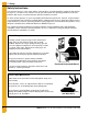
1. Safety Prepare for Emergencies Be prepared if fire starts. Keep a first aid kit and fire extinguisher handy. Keep emergency numbers for doctors, ambulance service, hospital, and fire department near your telephone. Keep Emergency Equipment Quickly Accessible Wear Protective Clothing Wear close-fitting clothing and safety equipment appropriate to the job. Eye Protection Remove all jewelry. Tie long hair up and back. Gloves Wear safety glasses at all times to protect eyes from debris.
1. Safety Safety Sign-Off Sheet As a requirement of O.S.H.A., it is necessary for the employer to train the employee in the safe operating and safety procedures for this auger. This sign-off sheet is provided for your convenience and personal record keeping. All unqualified persons are to stay out of the work area at all times. It is strongly recommended that another qualified person who knows the shut down procedure be in the area in the event of an emergency.
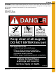
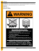
2. Decals ATTENTION: The decal shown below should be present on the outside of the door cover of the 2 ring, 24" porthole door cover and the roof manway cover. If a decal has been damaged or is missing in any of these locations, contact the manufacturer for a free replacement decal. GSI Decals 1004 E. Illinois St. Assumption, IL. 62510 Phone: 1-217-226-4421 Rotating flighting will kill or dismember. Flowing material will trap and suffocate. Crusted material will collapse and suffocate.
2. Decals ATTENTION: The decal shown below should be present on the outside of the door cover of the 2 ring, 24" porthole door cover and the roof manway cover. If a decal has been damaged or is missing in any of these locations, contact the manufacturer for a free replacement decal. GSI Decals 1004 E. Illinois St. Assumption, IL. 62510 Phone: 1-217-226-4421 WARNING DON’T DO UNLOADING INSTRUCTIONS: 1. Use CENTER FLOOR OUTLET ONLY until NO grain remains above this outlet. 2.
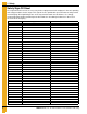
3. Installation 72' Full Floor Plank Layout Chart The following plank lengths start at the sidewall and work toward the center of the bin. Refer to grandstand support spacing on Page 22 for support spacing. 35'-7" from center of bin to edge of first plank.
3. Installation 75' Full Floor Plank Layout Chart The following plank lengths start at the sidewall and work toward the center of the bin. Refer to grandstand support spacing on Page 22 for support spacing. 37'-0.1/2" from center of bin to edge of first plank.
3. Installation 78' Full Floor Plank Layout Chart The following plank lengths start at the sidewall and work toward the center of the bin. Refer to grandstand support spacing on Page 22 for support spacing. 38' - 2-1/2" from center of bin to edge of first plank.
3. Installation 90' Full Floor Plank Layout Chart The following plank lengths start at the sidewall and work toward the center of the bin. Refer to grandstand support spacing on Page 22 for support spacing. 44'-7" from center of bin to edge of first plank.
3. Installation 105' Full Floor Plank Layout Chart The following plank lengths start at the sidewall and work toward the center of the bin. Refer to grandstand support spacing on Page 22 for support spacing. 51'-11" from center of bin to edge of first plank.
3. Installation Fan Placement Fans should be placed to provide the most uniform airflow and to minimize blockage of air flow by floor supports and unloading equipment. Consult with GSI for advice on specific cases. Figure 3A Grain Systems Recommended Method for Full Floor Installation This method should save floor construction time and eliminate problems of improper installation which could invalidate warranty. Dimension “A” is the leg-to-leg spacing along the centerline of a given plank.
3. Installation Grain Systems Recommended Method for Full Floor Installation (Continued) IMPORTANT: First piece of flooring must start the proper distance from centerline of bin. Refer to floor layout on Page 11 of correct bin diameter. First piece may have to be trimmed for proper distance. Figure 3B 5. Start at bin wall with shortest floor piece. Install support as per the spacing requirements of the grandstand support quantity chart on Pages 22-23.
3. Installation Installing the Undersplice The undersplice should be installed underneath the planks at the split after both plank lengths have been butted together. Each splice has to be laid as each row of planks are laid rather than after all have been placed. Figure 3C shows the layout of the undersplice plates and the screw pattern used to secure them.
3. Installation Installation Instructions 1. When a splice is needed, plank length A as described in the floor manual should be installed alongside plank length B. 2. The under-splice should then be installed under the split of plank A and B. The splice should extend 3" under each plank. The splice should be screwed in place as shown in Figure 3C on Page 18. 3. This process will be repeated for all plank locations requiring a splice.
3. Installation Flashing Installation Figure 3E Grain Systems Formed Flashing Installation If bin sweep auger is to be used, overlap flashing such that rotation (usually clockwise) of the sweep will climb up on the next flashing section. This will prevent the rotating/slipping outer wheel of the sweep from catching on the flashing edges. (See Figure 3E.) After the floor is in place, lay the flashing pieces on top of the floor place over the 1-1/4" bin bolts.
3. Installation Stiffener Flashing Support Instructions for Internal Stiffeners 1. Install the floor and support system, cutting the floor to go around the internal stiffeners as required. (See Figure 3G.) 2. Break the stiffener flashing support (SS-6984) into its three (3) components. 3. Lay the flashing supports on top of the flooring and weld the flashing supports to the stiffener as close as possible. Fasten the flashing to the wall, flashing support and floor, seal all spaces by welding or caulking.
4. 20 Gauge Grandstand Charts 20 Gauge Grandstand Chart - 2.66" Corrugation Narrow/2.66" Corrugation - 20 Gauge Grandstand Floor Support Chart Full Floor Supports Required for Plank Type Flooring 2.66" Corrugation (* Based Upon 13-1/2" or Taller Floor Heights) Dia. 12 15 18 21 24 27 30 33 36 39 42 45 48 54 60 72 75 78 90 105 Rings All floor styles OK for bin sizes in upper shaded area.
4. 20 Gauge Grandstand Charts 20 Gauge Grandstand Chart - 4.00" Corrugation Wide/4.00" Corrugation - 20 Gauge Grandstand Floor Support Chart Full Floor Supports Required for Plank Type Flooring 4.00" Corrugation (* Based Upon 13-1/2" or Taller Floor Heights) Dia. Rings 12 15 18 21 24 27 30 33 36 39 42 45 48 54 60 SUPPORT SPACING SUPPORT QUANTITY 72 75 78 90 105 All floor styles OK for bin sizes in upper shaded area.
NOTES 24 PNEG-1324 72', 75', 78', 90' and 105' Cor-Lok and Cut-Lok Flooring
5. Warranty GSI Group, LLC Limited Warranty The GSI Group, LLC (“GSI”) warrants products which it manufactures to be free of defects in materials and workmanship under normal usage and conditions for a period of 12 months after sale to the original end-user or if a foreign sale, 14 months from arrival at port of discharge, whichever is earlier.
This equipment shall be installed in accordance with the current installation codes and applicable regulations, which should be carefully followed in all cases. Authorities having jurisdiction should be consulted before installations are made. GSI Group 1004 E. Illinois St. Assumption, IL 62510-0020 Phone: 1-217-226-4421 Fax: 1-217-226-4420 www.gsiag.