2.66" Side Draw Instructions and 4.
2.66" SIDE DRAW INSTRUCTIONS PNEG-066 2.66" & 4.
2.66" Side Draw Systems Installation and Management Of Side Draw Systems Grain Systems designs and manufacturers bins to the highest standards, however proper installation and good usage practices for a commercial flume system are essential, regardless of manufacturer. The following practices address general usage and installation criteria for such systems. SIDE DRAW INSTALLATION SIDE DRAW MANAGEMENT AND USAGE 1.
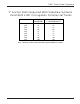
2.66" Side Draw Systems 1" Anchor Bolts Required With Sidedraw Systems Used With 2.66" Corrugation Commercial Tanks CORRUGATION 2.66" 2.66" 2.66" 2.66" 2.66" 2.66" 2.66" 2.66" 2.66" TANK DIAMETER 42' 48' 54 60' 72' 75' 78' 90' 105' TOTAL NUMBER OF 1" ANCHOR BOLTS 42 48 54 60 72 75 78 90 105 Use 1" diameter anchor bolts at all of the required stiffener locations. PNEG-066 2.66" & 4.
2.66" Side Draw Systems Additional Wind Rings Required For 2.
2.66" Side Draw Systems 2 POST WIND RING INSTALLATION (Viewed From Inside Of Bin) DISCHARGE TUBE INSTALLATION 1.) Use the bottom 2 holes in the last chute to locate discharge tube 28" below the 7th horizontal seam. Refer to Detail "C" for sidewall sheet hole dimensions. 2.) For proper water shed install plate so upper body sheet overlaps the plate, as shown in Detail "D". 3.) Use discharge tube assembly as a template, drill all holes 7/16" diameter. 4.
2.66" Side Draw Systems 3 Post (Viewed From Inside Of Bin) These instructions for 90' diameter tanks and smaller. See PNEG-972 or PNEG-1343 for 105' diameter tank sidedraw installation instructions. DISCHARGE TUBE INSTALLATION 1.) Use the bottom 2 holes in the last chute to locate discharge tube 28" below the 7th horizontal seam. Refer to Detail "C" for sidewall sheet hole dimensions. 2.) For proper water shed install plate so upper body sheet overlaps the plate, as shown in Detail "D". 3.
2.66" Side Draw Systems 2 & 3 Post (Internally Stiffened) DETAIL "A" 4" TYP. (10.16 cm) INSIDE OF BIN Field cutting of chutes is necessary to except the wind rings. Locate wind rings as shown. The wind ring must be assembled in to a complete ring and penetrate through the chute. Field drill stiffeners for attachment bracket. (IF REQUIRED) FIRST HORIZONTAL SEAM FROM EAVE STARTING LOCATION: 2nd INSIDE CORRUGATION OF THE 2nd RING FIELD DRILL SIDEWALL TO MATCH CHUTE. (7/16" DIA.
2.66" Side Draw Systems 2 & 3 Post (Externally Stiffened) NOTE: Unload tubes and supports from rack & pinion down are not provided by G.S.I. 11" (27.94 cm) 14.833" (37.68 cm) 19" (48.26 cm) STIFFENER COLUMN 7th SIDEWALL RING STIFFENER COLUMN 28-1/8" (71.44 cm) HORIZONTAL SEAM 6th SIDEWALL RING 5.333" (13.65 cm) 7" (17.78 cm) 14" (35.56 cm) FIELD CUT DISCHARGE HOLE 1-1/2" RADIUS AT CORNERS (3.80 cm) DETAIL "C" (EXTERNALLY STIFFENED) (2 POST) 19" 14.833" (37.
2.66" Side Draw Systems 2 & 3 Post (Externally Stiffened) 2.667" TYP. (6.77 cm) INSIDE OF BIN NOTE: Unload tubes and supports from rack & pinion down are not provided by G.S.I. FIRST HORIZONTAL SEAM FROM EAVE STARTING LOCATION: 2nd INSIDE CORRUGATION OF THE 2nd RING FIELD DRILL SIDEWALL TO MATCH CHUTE. (7/16" DIA. HOLES) CHUTE 8" TYP. (20.32 cm) DETAIL "A" (EXTERNALLY STIFFENED) 8th RING FROM TANK BASE CHUTE 7th HORIZONTAL SEAM FROM TANK BASE 7th RING FROM TANK BASE 8" (20.
4.00'' SIDE DRAW INSTRUCTIONS 12 PNEG-066 2.66" & 4.
4.00" Side Draw Systems Installation and Management Of Side Draw Systems in FCDL Series Bins/Silos Grain Systems designs and manufacturers bins to the highest standards, however proper installation and good usage practices for a commercial flume system are essential, regardless of manufacturer. The following practices address general usage and installation criteria for such systems. SIDE DRAW INSTALLATION SIDE DRAW MANAGEMENT AND USAGE 1.
4.00" Side Draw Systems FCL (4.00" CORR.) SIDE DRAW INSTRUCTIONS NUMBER OF RINGS 13 12 11 10 9 8 7 Rings 10 11 12 13 14 SIDE DRAW CHUTE INSTALLATION STARTING NUMBER HORIZONTAL LOCATION DIMENSION OF CHUTES FOR FIRST CHUTE 54" 10 MIDDLE OF SHEET 42" 9 MIDDLE OF SHEET 62" 7 MIDDLE OF SHEET 50" 6 MIDDLE OF SHEET 38" 5 MIDDLE OF SHEET 58" 4 MIDDLE OF SHEET 48" 3 MIDDLE OF SHEET 30' 1 1 W ind Ring Requirements 33' 36' 42' 1 1 1 1 1 1 1 1 1 1 1 48' 1 1 1 1 54' 1 1 1 ** 60' 1 1 1 ** PNEG-066 2.66" & 4.
4.00" Side Draw Systems NUMBER OF RINGS IN TANK FCL (4.00" CORR.) SIDE DRAW INSTRUCTIONS VIEWED FROM INSIDE TANK STARTING DIMENSION FOR FIRST CHUTE 13 12 11 SEE DETAIL "D" 1st BOLT HOLE IN TOP CHUTE REQUIRED SPACING BETWEEN CHUTE BOLT HOLES 10 8" 9 8 14" 5th HORIZONTAL SEAM FROM BASE 44" TYPICAL 15" 7 6 12-3/4" 17'-2" DETAIL "B" 5 STIFFENERS 4 3 WIND RING INSTALLATION 2 Installation of side draw systems on some 4.00" Corrugation tanks require additional wind rings.
4.00" Side Draw Systems Discharge Tube Installation 1. Use bottom holes in last chute to locate discharge tube. See Detail "B" for hole dimensions in sidewall sheet. (Approximately 14" below 5th horizontal seam.) 2. For proper watershed, install plate so upper body sheet overlaps plate as in detail "C". 3. Use discharge tube assembly for template. Drill all holes 3/8" diameter. 4.
4.00" Side Draw Systems Discharge Tube Installation 6th RING FROM BASE CHUTE FIRST HOLE IN 5th RING SIDE SHEET *MUST BE FIELD CUT* 4th RING FROM BASE 45° SIDE DRAW PLATE WELDMENT 4th HORIZONTAL SEAM FROM BASE DETAIL "C" STARTING DIMENSION FOR FIRST CHUTE 14" TOP SHEET DETAIL "D" USE MIDDLE TWO HOLES TO BOLT THE SIDEDRAW WELDMENT TO THE SIDEWALL. FIELD DRILL HOLES FOR BOLTS. FIELD CUT HOLE IN SIDEWALL FOR INSTALLATION OF SIDEDRAW WELDMENT. REFER TO THE SIDEDRAW INSTRUCTIONS FOR PROPER LOCATION.
4.00" Side Draw Systems NOTES 18 PNEG-066 2.66" & 4.
Limited Warranty The GSI Group, LLC. (“GSI”) warrants products which it manufactures to be free of defects in materials and workmanship under normal usage and conditions for a period of 12 months after sale to the original end-user or if a foreign sale, 14 months from arrival at port of discharge, whichever is earlier.
G.S.I . a Division of the The GSI Group, Inc. P.O. Box 20 1004 E. Illinois St. Assumption, IL 62510-0020 Phone: 217-226-4421 Fax: 217-226-4420 e-mail: gsi@grainsystems.com internet: http:\\www.grainsystems.