Vision Series Model 1100 Portable Dryers Parts Manual PNEG-1402 Date: 03-26-13 PNEG-1402
PNEG-1402 Vision Series Model 1100 Portable Dryers
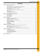
Table of Contents Contents Chapter 1 Main Structure Assembly ....................................................................................................................4 Frame Assembly ................................................................................................................................... 4 Frame, Auger Trough, Hopper Bulkheads and Metering Rolls ............................................................. 7 Inside (Plenum) Screens and Plenum Closure Doors .............
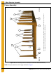
1. Main Structure Assembly The fan/heater end of the dryer is considered by GSI as the front end of the dryer. (The foreground of this photograph is the front end. Right and left sides are labeled above.) Right side 1 2 4 5 3 5 3 1a 5 3 4a 5 3 Left side Frame Assembly Figure 1A Frame Assembly (View from fan/heater end with hitch weldment removed.) NOTE: The parts pointed out on this page are listed on Page 6.
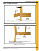
1. Main Structure Assembly Frame Assembly (Continued) 3 1 1a 4 2 4a NOTE: The right front corner is shown in the photo. For left front corner all parts are the same except for the hitch bracket (use 1a for the left side), and the frame rail (use 4a for the left side). Figure 1B Right Front Corner of Frame 3 5 4a 4 2 NOTE: The left rear corner is shown in the photo. For right rear corner all parts are the same except for the frame rail (use 4 for the right side).
1.
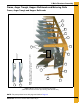
1. Main Structure Assembly Frame, Auger Trough, Hopper Bulkheads and Metering Rolls 10 7 6 9 5 4 NOTE: The hole pattern of the plenum closure door angles. This will distinguish between L.H. and R.H. 2 1 6 3 8 11 5 9 4 6 Frame, Auger Trough and Hopper Bulkheads Figure 1E Dryer Frame and Lower Basket Assembly (View from the front end of the dryer looking down the left side.) NOTE: The parts pointed out on this page are listed on Page 10.
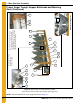
1. Main Structure Assembly 12 6 9 3 3 4 6 12 13 12 14 15 Center hanger bearing support and cross channel seal plate. 11a 5 12 3 9 6 4 20 19 6 Wooden meter roll support bearing. The meter roll sections are spliced together with a meter roll splice shaft (part #D31-0046) that passes through the support bearing assembly.
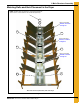
1. Main Structure Assembly Metering Rolls and their Placement in the Dryer NOTE: Ref #22 at the rear of dryer is a front section meter roll that is used as a rear section on 16 and 20 feet dryers only. 22 24 Meter roll bearing Ref #16, 17 and 18 on Page 10. 23 23 Meter roll bearing Ref #16, 17 and 18 on Page 10. 23 23 Meter roll bearing Ref #16, 17 and 18 on Page 10. 22 22 This end is the front (fan/heater) end of the dryer.
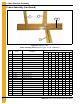
1. Main Structure Assembly Frame, Auger Trough, Hopper Bulkheads and Metering Rolls Parts List (See Figure 1E, 1F, and 1G) Qty Ref # Part # Description 1108T 1112 1114 1116 1118 1120 1122 1126 1 D01-1136Y Plenum Closure Door Angle, R.H. 3 5 6 7 8 9 10 12 2 D01-1136X Plenum Closure Door Angle, L.H.
1. Main Structure Assembly Inside (Plenum) Screens and Plenum Closure Doors Plenum Screens and Bulkheads (View from Front End) 2 3 4 3 5 1 5 6 16 7 10 8 7 11 13 14 18 9 19 20 12 15 10 20a 21 22 This photograph was taken before the front plenum end panel and outer screens were installed in order to get a good view of the inside screens and bulkheads. Plenum closure door. There are two (2) different plenum closure doors.
1.
1. Main Structure Assembly Outer Screens and Meter Roll Access Doors 3 3a * * 2 4 3 * 2 4 3 3a 5 1 9 10 6 14 12 7 13 8 9 10 11 See Figure 1K on Page 14 *NOTE: Ref #3 is pointing to the top edge angle gusset. There are two (2) types of gusset on the dryer. The photo on top right will help distinguish the difference between the two. The arrows are pointing to a tab on the gusset that makes them different (tabs are “bent” up in photo).
1. Main Structure Assembly Outer Screens and Meter Roll Access Doors (Continued) 19 15 16 18 17 20 Figure 1K Meter Roll Access Door Outer Screens and Meter Roll Access Doors Parts List (See Figure 1J and 1K) Ref # 14 Part # 1 D31-0307 Description Qty 1108T 1112 1114 1116 1118 1120 1122 1126 Column End Panel 4 4 4 4 4 4 4 4 2 D01-0113 Walk Rail Mounting Bracket 10 16 18 20 22 24 28 32 3 D01-0152 Top Edge Angle Gusset - L.H.
1. Main Structure Assembly Clean Out Doors 1 11 13 3 9 2 4 5 Front and rear handle mechanisms (rear shown in photo) 3 3a 11 5 4 2 10 6 7 Clean out door handle mechanism 11 NOTE: Ref #9, 10 and 11 together create the clean out door assembly. There are three (3) different clean out door assemblies that are used on GSI Network dryers: 1) 3 Column clean out door assembly (D51-0077). Ref #8a on the part # listing (Page 16). 2) 4 Column clean out door assembly (D11-0032).
1. Main Structure Assembly Clean Out Doors (Continued) 3a 14 1a 14 11 3a 4 2 5 14 Figure 1M Center Handle Mechanisms (This handle mechanism straddles the center cross channels.
1.
1. Main Structure Assembly Rear Access Doors 15 15 16 20 16 21 14 13 21 16 20 17 19 18 17 16 Rear access door (inside) Rear access door Figure 1O Front and Rear Plenum End Panels and Rear Access Doors Parts List (See Figure 1N and 1O) Ref # 18 Part # Description Qty 1108T 1112 1114 1116 1118 1120 1122 1a D01-2477 Column End Panel - L.H. Rear Grain Dryers 1 1 1 1 1 1 1 1126 1 1b D01-2476 Column End Panel - R.H.
1. Main Structure Assembly Fan Access Step 5 6 7 8 2 1 3 4 Figure 1P Fan Access Step Parts List Qty Ref # Part # Description 1-4 D01-1198 Fan Access Step Kit 1108T 1112 1114 1116 1118 1120 1122 1126 1 1 1 1 1 1 1 1 2 2 2 2 1 D01-1168 Fan Access Step L.H. Mount 1/Kit 2 D01-1166 Fan Access Step 1/Kit 3 D51-0022 Support, Control Panel 1/Kit 4 D01-1167 Fan Access Step R.H.
1.
1. Main Structure Assembly Bottom Auger 1 2 2 3 2 Bottom auger (View from center of dryer to the forward end.) 4 Bottom auger (View from center of dryer to the rear end.
1.
1.
1.
1. Main Structure Assembly Top Auger with Wet Bin Assembly Parts List (See Figure 1T and 1U) Qty Ref # Part # Description 1108T 1 D01-1521 Wet Bin Side, 4' Side Galv. Perf. 1 D01-1522 Wet Bin Side, 6' Side Galv. Perf.
2.
2.
2. Auger and Meter Roll Drive Trains Bottom Auger Drive Parts List (See Figure 2A and 2B) Qty Ref # Part # Description 1108T 1112 1114 1116 1118 1120 1122 1126 1 1 1 1 1 1 2 2 2 2 2 2 1 1 1 1 1 1 1 1 1 1 D01-1376 Bottom Front Angle Bracket 1 1 2 D02-0067 V-Belt BX85 2 2 2 MHC00490 V-Belt BX82 3 D02-0056 Sheave 2 Grade 3.35D x 5/8" Bore 3 D03-0174 Sheave 2.5D x 7/8" Bore 3 2818-2 Sheave 2 Grade 3.35D x 1-1/8" 3 D62-0003 Sheave 2 Grade 4.
2.
2.
2.
2.
3.
3.
3.
3. Fan/Heaters Air Mixer Assemblies 1 1a 2 Figure 3D Air Mixer Assemblies (36'' Air mixer shown in photo.
3. Fan/Heaters Flame Probe, Ignitor and Burner Assemblies 8 1 10 9 Ignitor and flame probe assemblies 7 2 6 3 4 5 Flame probe Ref #9 and 10 are used in LP fan/heaters only.
3.
3.
3.
3.
3. Fan/Heaters LP Pipe Train Assemblies (Continued) 23 25 24 2 1 10 1 4 3 2 7 2 8 5 6 23 9 22 19 12 13 2 11 21 20 17 17 18 16 12 14 15 40" and 42" LP pipe train assemblies 26 30 31 27 27 30 29 28 40'' and 42'' with 20 HP and smaller motors vaporizer coil connection and adjustment brackets. 40'' and 42'' with 25 HP and larger motors vaporizer coil connection and adjustment brackets.
3.
3.
3.
3.
3.
4. Dryer Electrical Conduits Upper Junction Box, Top Auger Motor Conduit and Operator Light 1 11 4 3 5 6 Top auger motor conduit 2 7 9 9 1 12 10 2 10 1 15 2 Upper junction box 11 8 Fill switch assembly (installed) Operator light 13 14 9 Ref #9-15 are components of the mercury switch box assembly (fill switch assembly) part #D01-0192.
4. Dryer Electrical Conduits Air Switch Assembly 3 7 9 4 8 2 5 6 Air switch assembly (internal parts) 1 Air switch assembly (D01-0672) 10 11 12 1-9 10 Air switch assembly (installed) Figure 4B Air Switch Assembly Parts List Ref # Part # 1-9 D01-0672 Description Air Switch Assembly Qty 1/Dryer 1 D01-0671 Air Switch Box Conduit Half 2/Assembly 2 D01-0670 Air Switch Box Face Plate 1/Assembly 3 DC-1103 Decal, Air Pressure Adjustment 1/Assembly 4 D03-0177 Grommet, 11/16" I.D.
4. Dryer Electrical Conduits Right and Left Grain and Plenum High-Limits Left grain high-limit Right grain high-limit 8 11 Plenum high-limit 7 10 Right grain and plenum high-limit thermostat enclosures 4 9 Left grain high-limit thermostat enclosure Grain temperature thermistor. There are two (2) thermistors in each (right and left) grain high-limit thermostat assemblies.
4.
4. Dryer Electrical Conduits Lower Junction Box, Meter Roll Motor Conduit and Rear Discharge Conduit 7 3 8 5 4 9 6 6 2 5 1 7 2 1 Conduit to meter roll motor. (See Meter roll motor conduit connection below.) 4 10 8 1 Lower junction box (right) Lower junction box (left) Conduit to meter roll speed sensor and rear discharge switch. (See photos below and on Page 53.
4.
5.
5. Control Boxes Fan/Heater Electrical Box Parts List (See Figure 5A) Ref # Part # Description D01-1992 Control Box Lid 1 1 D01-2105 Control Box Back Panel 1 2 D01-2106 Control Left Side 1 3 D01-2107 Control Box Right Side 1 4 D01-2110 Control Box Front Panel 1 5 D03-0696 Control Box Latch 1 6 D01-2108 Control Box Base 1 7 006-1389-3 Nylon Bushing - 2" Diameter 1 8 D01-2111 Control Box Wall 1 9 E160-1137 Ground Lug, #TA-2 2 10 HH-1105 Nylon Bushing - 11/16" I.D.
5.
5. Control Boxes Lower Control Box Back Panel 1 9 13 14 4 5 6 7 8 10 5 11 Emergency stop switch (outside) 2 12 10 3 Emergency stop switch (inside) 15 Lower control box back panel Figure 5C Lower Control Box Back Panel Parts List Ref # Part # Description Circuit 1 D01-0486 Lower Control Box Back Panel Misc. 2 D03-0742-C Vision Control 12 VDC Power Supply Control 3 D03-0754-C Touch Control 5 VDC Power Supply Control 4 D03-0013 Din Rail, Terminal Block Mounting Misc.
5. Control Boxes Control Box Switch Panel (Rear) 1 A more detailed parts breakdown of the display and computer is shown on Page 59. 9 2 6 3 4 1a 5 Vision control panel (rear) 7 7 8 8 7 Detailed view of a two position switch Detailed view of a single position switch Figure 5D Control Box Switch Panel (Rear) Parts List Ref # 58 Part # Description Circuit 1 TFH-2046 Spring Latch Southco w/ Black Knob Misc. 1a TF-1519 Latch, Southco Slotted Misc.
5.
5.
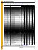
5. Control Boxes Upper Control Box Component Part Numbers (Continued) 1108T Upper Control Box Component Parts List (See Figure 5F) 1108T Part # Ref # Description 220V 1 PH 208V 3 PH 220V 3 PH 440V 3 PH Circuit 575V 3 PH 1 D01-0480 D01-0480 D01-0480 D01-0480 D01-0480 Power Box Bock Panel N/A 2 D03-0473 D03-0473 D03-0472 D03-0471 D03-0543 Overload Load 3 D03-0482 D03-0479 D03-0477 D03-0474 D03-0473 Overload Load Aux.
5. Control Boxes Upper Control Box Component Part Numbers (Continued) 1112 Upper Control Box Component Parts List (See Figure 5F) 1112 Part # Ref # Description 220V 1 PH 62 208V 3 PH 220V 3 PH 440V 3Ph Circuit 575V 3Ph 1 D01-0480 D01-0480 D01-0480 D01-0480 D01-0480 Power Box Bock Panel N/A 2 D03-0475 D03-0473 D03-0473 D03-0471 D03-0471 Overload Load 3 D03-0482 D03-0479 D03-0477 D03-0474 D03-0473 Overload Load Aux.
5. Control Boxes Upper Control Box Component Part Numbers (Continued) 1114 Upper Control Box Component Parts List (See Figure 5F) 1114 Part # Ref # Description 220V 1 PH 208V 3 PH 220V 3 PH 440V 3 PH Circuit 575V 3 PH 1 D01-0480 D01-0480 D01-0480 D01-0480 D01-0480 Power Box Bock Panel N/A 2 D03-0477 D03-0475 D03-0474 D03-0473 D03-0471 Overload Load 3 D03-0483 D03-0480 D03-0479 D03-0475 D03-0475 Overload Load Aux.
5. Control Boxes Upper Control Box Component Part Numbers (Continued) 1116 Upper Control Box Component Parts List (See Figure 5F) 1116 Part # Ref # Description 220V 1 PH 64 208V 3 PH 220V 3 PH 440V 3 PH Circuit 575V 3 PH 1 D01-0480 D01-0480 D01-0480 D01-0480 D01-0480 Power Box Bock Panel N/A 2 D03-0478 D03-0479 D03-0475 D03-0473 D03-0472 Overload Load 3 D03-0483 D03-0480 D03-0479 D03-0475 D03-0475 Overload Load Aux.
5. Control Boxes Upper Control Box Component Part Numbers (Continued) 1118 Upper Control Box Component Parts List (See Figure 5F) 1118 Part # Ref # Description 208V 3 PH 220V 3 PH 440V 3 PH Circuit 575V 3 PH 1 D01-0480 D01-0480 D01-0480 D01-0480 Power Box Bock Panel N/A 2 D03-0479 D03-0475 D03-0473 D03-0472 Overload Load 3 D03-0480 D03-0479 D03-0475 D03-0475 Overload Load Aux.
5. Control Boxes Upper Control Box Component Part Numbers (Continued) 1120 Upper Control Box Component Parts List (See Figure 5F) 1120 Part # Ref # Description 208V 3 PH 66 220V 3 PH 440V 3 PH Circuit 575V 3 PH 1 D01-0480 D01-0480 D01-0480 D01-0480 Power Box Bock Panel N/A 2 D03-0479 D03-0477 D03-0474 D03-0473 Overload Load 3 D03-0483 D03-0483 D03-0477 D03-0476 Overload Load Aux.
5. Control Boxes Upper Control Box Component Part Numbers (Continued) 1122 Upper Control Box Component Parts List (See Figure 5F) 1122 Part # Ref # Description 208V 3 PH 220V 3 PH 440V 3 PH Circuit 575V 3 PH 1 D01-0480 D01-0480 D01-0480 D01-0480 Power Box Bock Panel N/A 2 D03-0479 D03-0477 D03-0474 D03-0473 Overload Load 3 D03-0483 D03-0483 D03-0477 D03-0476 Overload Load Aux.
5. Control Boxes Upper Control Box Component Part Numbers (Continued) 1126 Upper Control Box Component Parts List (See Figure 5F) 1126 Part # Ref # Description 208V 3 PH 68 220V 3 PH 440V 3 PH Circuit 575V 3 PH 1 D01-0480 D01-0480 D01-0480 D01-0480 Power Box Bock Panel N/A 2 D03-0480 D03-0479 D03-0475 D03-0475 Overload Load 3 D03-0483 D03-0483 D03-0477 D03-0476 Overload Load Aux.
6. Warranty GSI Group, LLC Limited Warranty The GSI Group, LLC (“GSI”) warrants products which it manufactures to be free of defects in materials and workmanship under normal usage and conditions for a period of 12 months after sale to the original end-user or if a foreign sale, 14 months from arrival at port of discharge, whichever is earlier.
This equipment shall be installed in accordance with the current installation codes and applicable regulations, which should be carefully followed in all cases. Authorities having jurisdiction should be consulted before installations are made. GSI Group 1004 E. Illinois St. Assumption, IL 62510-0020 Phone: 1-217-226-4421 Fax: 1-217-226-4420 www.gsiag.