Digital High / Low Thermostat INSTALLATION AND OPERATION PNEG-1499 PNEG-1499 Date: 10-05-07 PNEG-1499 High / Low Thermostat 1
CHECK LIST _____ 1. All wire connections _____ 2. Factory values programmed _____ a. Value 1 set to ( F ) _____ b. Value 2 or “S1” set to ( 100 ) _____ c. Value 3 or “DIF1” set to ( 5 ) _____ d. Value 4 set to ( H1 ) _____ e. Value 5 or “S2” set to ( 130 ) _____ f. Value 6 or “DIF2” set to ( 5 ) _____ g. Value 7 set to ( H2 ) _____ 3. All items included in packaging. _____ 4. Safety Decal Installed on side of Thermostat _____ 5. Aesthetic appearance _____ 6. Manual _____ 7.
TABLE OF CONTENTS Safety ....................................................................................................... 4 Safety Guidelines ........................................................................... 4 Safety Decals ................................................................................. 7 Roof Damage Warning and Disclaimer .......................................... 8 Installation .............................................................................................
SAFETY SA FET Y GU I DEL I N ES This manual contains information that is important for you, the owner/operator, to know and understand. This information relates to protecting personal safety and preventing equipment problems. It is the responsibility of the owner/operator to inform anyone operating or working in the area of this equipment of these safety guidelines. To help you recognize this information, we use the symbols that are defined below. Please read the manual and pay attention to these sections.
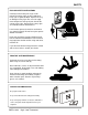
SAFETY FOLLOW SAFETY INSTRUCTIONS Carefully read all safety messages in this manual and safety signs on your equipment. Keep signs in good condition. Replace missing or damaged safety signs. Be sure new equipment components and repair parts include the current safety signs. Replacement safety signs are available from the manufacturer. Learn how to operate the machine and how to use controls properly. Do not let anyone operate without instruction. Keep your machinery in proper working condition.
SAFETY WEAR PROTECTIVE CLOTHING Hearing Protection Wear close fitting clothing and safety equipment appropriate to the job. Ear Plugs or Muffs should be worn at all times to protect ears from high noise levels. Safety glasses should be worn at all times to protect eyes from debris. Wear gloves to protect your hands from sharp edges on plastic or steel parts. A respirator may be needed to prevent breathing potentially toxic fumes and dust.
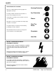
SAFETY DECALS Safety decals should be read and understood by all people in the grain handling area. If a decal is damaged or is missing contact: The GSI Group, Inc. 1004 E. Illinois St. Assumption, IL 62510 217-226-4421 A free replacement will be sent to you. Part Number: DC-889 Size: 2.813” x 1.375” Located on side of thermostat.
SAFETY Roof Damage Warning And Disclaimer GSI DOES NOT WARRANT ANY ROOF DAMAGE CAUSED BY EXCESSIVE VACUUM OR INTERNAL PRESSURE FROM FANS OR OTHER AIR MOVING SYSTEMS. ADEQUATE VENTILATION AND/OR "MAKEUP AIR" DEVICES SHOULD BE PROVIDED FOR ALL POWERED AIR HANDLING SYSTEMS. GSI DOES NOT RECOMMEND THE USE OF DOWNWARD FLOW SYSTEMS (SUCTION). SEVERE ROOF DAMAGE CAN RESULT FROM ANY BLOCKAGE OF AIR PASSAGES. RUNNING FANS DURING HIGH HUMIDITY/COLD WEATHER CONDITIONS CAN CAUSE AIR EXHAUST OR INTAKE PORTS TO FREEZE.
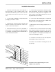
INSTALLATION Installation Instructions 1. Mount the thermostat control on the right side of 5. Use the S-280 screws provided to mount the C-8058 the fan transition. Locate a suitable location on the plate on the sidewall. The large hole on the plate should bin wall that will allow the power cord to reach the be centered on a valley of the bin corrugations. The heater and the control to be at eye level for easy ac- plate should be mounted approximately in the center of cess.
ELECTRICAL CONNECTION Standard electrical safety practices and codes should be used when working with a heater. Refer DANGER to the National Electric Code Standard Handbook ALWAYS DISCONNECT AND LOCK OUT POWER by the National Fire Protection Association. A quali- BEFORE WORKING ON OR AROUND HEATER. fied electrician should make all wiring installations. Thermostat Connection to Standard Terminal Strip on heaters built prior to 2007. 1. Connect power cord to fan control box. 2.
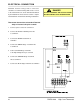
ELECTRICAL CONNECTION Thermostat Connection to Standard Terminal Strip on heaters built in 2007 to present. 5. Connect the RED Stage 1 N/O wire to the high/low light and cycle solenoid. 1. Connect power cord to fan control box. 6. Connect the ORANGE Stage 2 Common 2. Connect the BLACK 120VAC power wire wire to terminal 1. to the ON / OFF switch. Make this connection so this switch will also control the thermostat power. 7.
ELECTRICAL CONNECTION Thermostat Connection to HF-7318 Circuit Board 4. Connect the BLUE Stage 2 Common wire to terminal 15. 1. Connect power cord to fan control box. 5. Connect the ORANGE Stage 2 N/O wire to 2. Connect the BLACK 120VAC power wire terminal 14. to terminal 20. 6. Connect the RED Stage 1 N/O wire to 3. Connect the WHITE Neutral wire to terminal 13. terminal 19. 7. Connect the GREEN Stage 1 Common wire to terminal 12.
PROGRAMMING Programming Set Points Programming can be done anytime that the thermostat control is receiving power, even when the heater is in operation. 1. Press the SET key once to set temperature scale mode. Use the UP or DOWN arrow key to toggle between F for degrees Fahrenheit or C for degrees Celsius. 2. Press the SET key again. “S1” should now flash at the left side of the screen. Press the UP arrow to increase or the DOWN arrow to decrease the setpoint to the desired temperature.
PARTS HF-8056 14 THERMOSTAT ASY HI-LO 2-STAGE DIGITAL Key Qty Part Number Description 1 1 HF-8055 THERMOSTAT 2-STAGE DIGITAL 2 2 FH-1309 LOCK NUT 1/2" #401 ARL.
APPENDIX NOTE: Refer to Documentation provided by component manufacturer for troubleshooting and maintenance of the Thermostat Control including sensor data. Form No. 7515006-001 Rev B. Troubleshooting Error Messages. E1 Appears when either the up arrow or down arrow key is pressed when not in the programming mode. To Correct: If the E1 message appears even when no keys are being pressed, replace the control. E2 Appears if the control settings are not properly stored in memory.
PNEG-1499 High / Low Thermostat
Limited Warranty The GSI Group, LLC. (“GSI”) warrants products which it manufactures to be free of defects in materials and workmanship under normal usage and conditions for a period of 12 months after sale to the original end-user or if a foreign sale, 14 months from arrival at port of discharge, whichever is earlier.
This Equipment shall be installed in accordance with the current installation codes and applicable regulations which should be carefully followed in all cases. Authorities having jurisdiction should be consulted before installation occurs. Revisions: 10/05/07 Updated all drawings and instructions for wiring Stage 1 as Cycle and Stage 2 as High Limit. Included instructions for wiring to new heaters using HH-1089E Time Delay.