200 Vision X-Stream Series Portable Dryers Parts Manual PNEG-1616 Date: 09-22-10 PNEG-1616
PNEG-1616 1200 VISION X-STREAM PARTS MANUAL
Table of Contents MAIN STRUCTURE ASSEMBLY.....................................................................................5 FRAME ASSEMBLY.......................................................................................................................................................5 FRAME, LOWER BASKET , AND METERING ROLLS........................................................................................ ........8 PLENUM (INSIDE) SCREENS AND METER ROLL UPPER SHIELD..........................
PNEG-1616 1200 VISION X-STREAM PARTS MANUAL
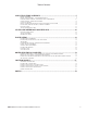
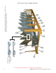
4a Right side 1 2 4 5 5 3 1a 5 3 3 Frame Assembly (view from fan/heater end with hitch weldment removed). 5 3 Left side Frame **NOTE: The parts pointed out on this page are listed on page 7.
Frame Right front corner of frame. **NOTE: The right front corner is shown in the photo. For left front corner all parts are the same except for the Hitch Bracket (use 1a for the left side), and the Frame Rail (use 4a for the left side). 3 1 1a 2 4 4a Left rear corner of frame.
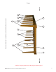
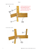
Frame Center cross ties.
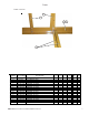
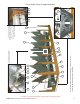
Note the hole pattern of the plenum closure door angles. This will distinguish between L.H. and R.H. 8 7 2 1 6 9 5 10 4 6 3 8 11 5 9 4 6 Dryer frame and lower basket assembly (view from the front end of the dryer looking down the left side). Frame, Auger Trough, & Hopper Bulkheads **NOTE: The parts pointed out on this page are listed on page1.
PNEG-1616 1200 VISION X-STREAM PARTS MANUAL 4 13 9 3 12 6 14 15 12 3 11a Dryer frame and lower basket assembly (view from the rear end of the dryer looking up the right side). 6 12 5 12 Center hanger bearing support and cross channel seal plate. 9 6 3 6 20 19 Discharge bearing plate. 4 Wooden meter roll support bearing. The meter roll sections are spliced together with a meter roll splice shaft (part no. D310046) that passes through the support bearing assembly .
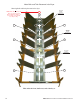
Meter Rolls and Their Placement in the Dryer Metering Rolls and their placement in the dryer . NOTE: Item 22 at the rear of dryer is a front section meter roll that is used as a rear section on 16 and 20 foot dryers only. Meter Roll Bearing See pg. 11 Items 16, 17, 18 22 24 23 23 Meter Roll Bearing See pg. 11 Items 16, 17, 18 23 23 Meter Roll Bearing See pg. 11 Items 16, 17, 18 22 22 This end is the front (fan/heater) end of the dryer.
Meter Rolls and Their Placement in the Dryer ITEM NUMBER PART NUMBER 1 2 3 4 5 6 7 8 9 10 11 11 11 11 11 11 11A 11A 11A 11A 11A 11A 12 13 14 15 16 17 18 19 20 21 22 23 24 D01-1136Y D01-1136X D01-0109 D01-0004 D01-0005 D01-0007 D01-0011 D01-0012 D01-0008 D01-1374 D21-0011-PP D01-0538-PP D31-0044-PP D61-0002-PP D101-0002-PP D71-0001-PP D21-0010-PP D01-0537-PP D31-0043-PP D61-0001-PP D101-0001-PP D71-0002-PP D01-0048 D01-1512 D01-1291 D01-1290 D02-0028 D31-0148 D02-0061 D01-0177 D01-1511 D31-0120 D31-0031
Inside (Plenum) Screens, Plenum Closure Doors Plenum screens and bulkheads (view from front end). 3B 2 1 4 3A 5 5 6 16 7 8 10 7 11 13 15 14 18 19 9 12 20 20a 10 This photograph was taken before the front plenum end panel and outer screens where installed in order to get a good view of the inside screens and bulkheads. 21 22 12 Plenum closure door. There are two different plenum closure doors.
Meter Roll Upper Shield Assembly Close up of of meter roll upper shield assembly .
Outer Screens, & Meter Roll Access Door Outer screens (view from front end). 2 * 4 * 3 * 3a 3 3 3a 2 4 5 1B 1A 13 14 6 18 17 11 12 13 14 15 *Note: Item 3 is pointing to the top edge angle gusset. There are two types of gusset on the dryer . The photo above will help distinguish the difference between the two. The arrows are pointing to a tab on the gusset that makes them different (tabs are “bent” up in photo). Item 3a is used in two places only; 1.) front right of dryer 2.
Plenum Divider Plenum divider. Plenum divider clean-out door. 9 10 9 7 8 The photo above and on page 16 was taken before plenum end panels where installed.
Clean Out Doors Front and rear handle mechanisms (rear shown in photo). *Note: Items 9, 10, & 11 together create the clean out door assembly. There are three different clean out door assemblies that are used on GSI Network dryers: 1.) 3 column clean out door assy. (D51-0077). Item 8a on the part no. listing (pg 17). 1 2.) 4 column clean out door assy. (D11-0032). Item 8b on the part no. listing (pg 17). 3 2 4 13 3.) 5 column clean out door assy. (D01-0349). Item 8c on the part no. listing (pg 17).
Clean Out Doors Center handle mechanisms (this handle mechanism stradles the center cross channels). 3a 14 1a 14 4 2 5 ITEM NUMBER PART NUMBER 1 1a 2 3 3a 4 5 6 7 8a 9 10 11 8b 9 10 11 D01-0264 D31-0162 D01-0296 D01-0261 D01-0293 D01-0294 S-4378 S-248 S-7241 D51-0077 D21-0005 D21-0012 D01-0308 D11-0032 D31-0021 D31-0130 D01-0308 PIVOT ROD 25.188" PIVOT ROD 49.
Front & Rear Plenum End Panels, & Upper & Lower Rear Access Doors Rear end panels & support arms. 2 5 1D Front end panels & support arms.
Front & Rear Plenum End Panels, & Upper & Lower Rear Access Doors Upper plenum access door. Lower plenum access door. 14 9 15 11 15 13 13 10 10 15 9 12 16 15 11 Upper plenum access door (inside). Lower plenum access door (inside).
Fan Guards, Support Panels, Ladder Assembly 1 4 5 2 3 20 ITEM NUMBER PA RT NUMBER DESCRIPTION 1 2 2 3 3 4-5 D01-2400-Y F-7062-Y F-7060-Y CD-0575 CD-0576 410-1577-7 SUPPORT PA NEL-FRONT 28 OPP FA N V ENTURI: 26" V ENTURI: 28" GRILL GUA RD: CD-26 GRILL GUA RD: CD-28 LA DDER A SSEMBLY - 10' 7" 4 5 D01-1919 D61-0096 LA DDER RA IL 12 RUNG UNIV ERSA L LA DDER RUNG 1214 1216 1218 1 1 1 1 1 1 2 2 2 1220 1 1222 1 1226 1 1 1 1 1 2 1 2 1 2 2/A SSEMBLY 12/A SSEMBLY PNEG-1616 1200 VI
Fan Guards, Support Panels, Ladder Assembly 1 2 3 Ladder Assembly shown on page 20.
Bottom Auger Bottom Auger (view from center of dryer to the Bottom Auger (view from center of dryer to the forward end). rear end). 1 2 2 3 2 4 Bottom Auger center bearing andsupport. 5 22 7 Bottom Auger rear bearing.
Bottom Auger Rear Discharge Box. Auger bearing.
Top Auger With Wet Bin Assembly 2 1 1 Top Auger with wet bin (switch paddle end). 3 6 5 4 7 8 1 3 11 9 10 12 26 9 13 14 14a Top Auger (fill end).
Top Auger With Wet Bin Assembly Top Auger bearing support. 15 Top Auger bearing support (inside view).
Bottom Auger Drive Bottom Auger drive components 1 9 10 2 8 3 7 4 6 5 11 11 Bottom Auger motor and motor mount. 12 Forward drive tension adjustment. 13 5 13 Rear drive tension adjustment.
Bottom Auger Drive Bottom auger and metering roll drive guard. 21 22 19 20 ITEM NUMBER PA RT NUMBER DESCRIPTION 1 D01-1376 BOTTOM FRONT A NGLE BRA CKET 2 MHC00490 BELT-V BX82 3 2818-2 SHEA V E 2GR 3.35Dx1 1/8" 3 D62-0003 SHEA V E 2GR 4.
Top Auger Drive 1 6 Belt guard upper mount. 1 4 2 3 5 Top Auger drive components. 12 13 Top Auger belt guard cover.
Top Auger Drive 7 8 9 10 11 Top Auger motor and motor mount. ITEM NUMBER PA RT NUMBER DESCRIPTION 1214 1 D01-0453 TOP A UGER BELTGA RD BODY 1 2 D52-0001 SHEA V E 2GR 16" GRIPBELT 1 3 D32-0019 BUSHING Q1-1 1/2" SPLIT TA PER 1 4 D01-0464 BELT-V BX97 2 5 2818-2 SHEA V E 2GR 3.35Dx1 1/8" BORE 1 5 D62-0003 SHEA V E 2GR 4.25Dx1 3/8" 6 D01-0155 MOUNTING BRA CKET-BELT GD SPCR 1 7 D01-0424 DRY ER TOP HA ND HOLD 1 *8 D03-1109 MOTOR 5HP 1PH 1800RPM 1 8 500-3 MOTOR 5HP 3PH 1800RPM 1 *8 D03-1010 MOTOR 7.
Metering Roll Drive SCR Motor/Reduction drive and motor mount assembly. 8 1 7 2 3 4 5 6 Meter roll drive train components.
Metering Roll Drive Front meter roll bearing. Rear meter roll bearing.
Fan Heater Housing Assembly Fan Heater housing assembly. 26” & 28” burner support and collector cup. 9 1 10 2 3 10a 9a 36”-42” burner support and collector cup.
Fan Heater Housing Assembly BOTTOM FANS ITEM NUMBER PART NUMBER 1 1 1 1 1 2 2 2 3 3 3 3 4 5 6 7 8 9 9 9a 9a 9a 10 10 10a 10a 10a D01-1995 D01-1996 D01-1963 D01-1997 D01-1964 D01-0651 D01-0529 D01-1452 D01-0528 D01-1480 D01-1479 D01-1451 401-5759-6-B 069-1303-2 DC-1224 DC-1225 DC-1227 HF-986 HF-983 D01-1484 D01-1485 TF-1217 HF-978 HF-7092 D01-1482 D01-1483 TF-1216 DESCRIPTION WRAPPER, 26" FAN HEATER WRAPPER, 28" FAN HEATER WRAPPER, 36" FAN HEATER WRAPPER, 40" FAN HEATER WRAPPER, 42" FAN HEATER STRAIGHTE
Fan Motor, Motor Mount, & Fan Blade Fan motor and motor mount. 1 FAN HEATER; (Dia., HP) 26" 12Hp 28" 12Hp Fan blade and bushing.
Air Mixer Assemblies Air mixer assemblies (36” air mixer shown in photo). 1 1a 2 ITEM NUMBER PART NUMBER 1-2 1 1a 2 1-2 1 1a 2 1-2 1&1a 2 1-2 1&1a 2 1-2 1&1a 2 D01-0969 D01-0968 D01-0967 CD-0228 D01-0955 D01-0951 D01-0950 CD-0228 CD-0113 D01-1303 CD-0083 CD-0117 D01-1218 CD-0083 CD-0118 CD-0192 CD-0083 DESCRIPTION AIR MIXER ASSEMBLY, 26" AIRMIXER CAN, 26" x 15" LONG AIRMIXER CAN, 26" x 8" SHORT SMALL DIA.
Flame Probe, Ignitor, and Burner Assemblies 8 1 Ignitor 2 7 3 6 5 Flame probe 4 9 10 Items 9 and 10 are used in LPFan/Heaters only. ITEM 10 10 10 10 PART No. CD-0414 HF-7207 HF-7251 HF-7319 DESCRIPTION VAPORIZOR COIL 26 28" 3 WRAP VAPORIZER COIL 36-42"10-17HP VAPORIZER 3/4" 3 WRAP 36-42" VAPOR COIL (SPIRAL) 42" 40HP 2612 2812 3615 4015 4220 4225 4230 4240 1 1 1 1 1 1 1 1 Burner housing high limit switch. 11 12 13 28” Fan heater burner assembly. 14 15 26” Fan heater burner assembly.
Flame Probe, Ignitor, and Burner Assemblies 36” Fan heater burner assembly. 40” &42” Fan heater burner assembly.
LP Pipe Train Assemblies 26” & 28” Fan heater LPpipe train assembly. 24 25 26 10 4 1 11 2 3 4 23 24 5 6 7 8 9 18 21 13 2 12 11 14 20 17 19 17 22 16 12 15 26” & 28”Vaporizer coil connection and adjustment brackets.
LP Pipe Train Assemblies ITEM NUMBER PART NUMBER DESCRIPTION 26" FAN 28" FAN 1 THH-4120 ELBOW, 3/4" - 90 DEG SCH 40 * 1 2 THH-4121 NIPPLE, 3/4" CLOSE SCH 40 2 2 3 007-1048-3 BALL VALVE, 3/4" W/LEVER HANDLE 1 1 4 THH-4125 NIPPLE, 3/4" x 2 SCH 40 2 2 5 THH-4154 TEE, 3/4" x 3/4" x 1/4" SCH 40 1 1 6 HH-2984 GUAGE, PRESSURE 0-30# LP 1 1 7 THH-4136 NIPPLE, 3/4" x 3" SCH 40 1 1 8 056-2223-8 VALVE, SOLENOID 3/4"NPT 115V DIN 1 1 9 056-2228-7 VALVE, SOLENOID 3/4"NPT 115V
LP Pipe Train Assemblies 36” Fan heater LPpipe train assembly. 24 25 26 10 4 1 2 3 4 23 24 5 6 7 8 9 18 21 13 2 12 11 14 20 17 19 17 22 16 12 15 36” Vaporizer coil connection and adjustment brackets.
LP Pipe Train Assemblies ITEM NUMBER PART NUMBER 1 THH-4120 ELBOW, 3/4" - 90 DEG SCH 40 2 THH-4121 NIPPLE, 3/4" CLOSE SCH 40 2 3 007-1048-3 BALL VALVE, 3/4" W/LEVER HANDLE 1 4 THH-4125 NIPPLE, 3/4" x 2 SCH 40 2 5 THH-4154 TEE, 3/4" x 3/4" x 1/4" SCH 40 1 6 HH-2984 GUAGE, PRESSURE 0-30# LP 1 7 THH-4136 NIPPLE, 3/4" x 3" SCH 40 1 8 056-2223-8 VALVE, SOLENOID 3/4"NPT 115V DIN 1 DESCRIPTION 36" LP F/H 1 9 056-2228-7 VALVE, SOLENOID 3/4"NPT 115V BYP 1 10 THH-4066 ELBOW 3
LP Pipe Train Assemblies 40” & 42” LP pipe train assemblies. 23 24 25 2 1 10 1 2 3 2 4 8 7 5 6 23 9 17 22 19 12 13 2 21 20 18 17 16 14 12 11 15 40” & 42” with 25hp and larger motors vaporizer coil connection and adjustment brackets. 40” & 42” with 20hp and smaller motors vaporizer coil connection and adjustment brackets.
LP Pipe Train Assemblies ITEM NUMBER PART NUMBER 1 2 3 4 5 6 7 8 9 10 11 12 13 14 15 16 17 18 19 20 21 22 23 24 25 26 27 28 29 30 31 DESCRIPTION THH-4115 ELBOW, 1" -90 DEG SCH 40 007-1104-4 NIPPLE, CLOSE 1" 007-1296-8 BALL VALVE, 1" WITH LEVER HANDLE 007-1106-9 TEE, 1" x 1" x 3/4" D07-0027 REDUCER, 3/4"-1/4" HEX BUSHING HH-2984 PRESSURE GUAGE, 0-30# LP THH-4037 NIPPLE, 1" x 2 1/2" SCH 40 056-2224-6 VALVE, SOLENOID 1" NPT 115V DIN 056-2230-3 VALVE, SOLENOID 1" NPT 115V BYPASS 007-1242-2 NIPPLE, 1" x 2" SCH
NG Pipe Train Assemblies 26” & 28” Fan heater NG pipe train assembly .
NG Pipe Train Assemblies 36” Fan heater NG pipe train assembly . 12 13 14 2 8 7 1 2 3 2 4 7 9 5 6 10 11 ITEM NUMBER PART NUMBER 1 2 3 4 5 6 7 8 9 10 11 12 13 14 007-1307-3 007-1104-4 007-1296-8 007-1106-9 D07-0027 D08-0022 007-1242-2 THH-4115 056-2224-6 056-2230-3 THH-4164 326-1047-9 401-5503-8 401-5255-5 DESCRIPTION ELBOW, 1" - 3/4" NIPPLE, CLOSE 1" BALL VALVE, 1" W/LEVER HANDLE TEE, 1" x 1" x 3/4" REDUCER, 3/4" - 1/4" HEX BUSHING GAUGE, PRESSURE 0-15# NIPPLE, 1" x 2" SCH 40 ELBOW, 1"-90 DEG.
NG Pipe Train Assemblies 40” & 42” Fan heater NG pipe train assembly . 11 12 13 2 1 7 1 2 3 2 4 7 9 5 6 10 8 46 ITEM NUMBER PART NUMBER 1 THH-4115 ELBOW, 1" - 90 DEG SCH 40 2 007-1104-4 NIPPLE, CLOSE 1" 3 3 007-1296-8 BALL VALVE, 1" W/LEVER HANDLE 1 4 007-1106-9 TEE, 1" x 1" x 3/4" 1 5 D07-0027 REDUCER, 3/4" - 1/4" HEX BUSHING 1 6 D08-0022 GAUGE, PRESSURE 0-15# 1 7 007-1242-2 NIPPLE, 1" x 2" SCH 40 2 8 THH-4164 ELBOW, 1"-90 DEG.
Fan Heater Orifices LIQUID PROPANE ORIFICES FAN HEATER ORIFICE SIZE PART NUMBER 26"12hp .2188" HF-7087 HF-7587 PIPE FOR 26" FAN HEATER ORIFICE 28"12hp .25" THF-3241 36"12hp .2813" THF-3242 36"15hp .3281" CD-0150 40"15hp .3438" THF-3058 42"20hp .375" THF-3247 42"25hp .3906" THF-3249 NATURAL GAS ORIFICES FAN HEATER ORIFICE SIZE PART NUMBER 26"12hp .3125" HF-7099 PIPE FOR 26" FAN HEATER ORIFICE HF-7587 28"12hp .375" THF-3140 36"12hp .4063" THF-3243 36"15hp .5" THF-3244 40"15hp .5156" THF-3246 42"20hp .
LP Supply Line Front LP supply line. Rear LP supply line. 8 14 1 13 2 12 2 6 5 11 7 3 9 4 5 48 8 ITEM No. PA RT No.
NG Supply Line Natural gas fuel supply line. Supply line mounting brackets.
Upper Juntion Box, Top Auger Motor Conduit, & Operator Light Top auger motor conduit. Upper junction box. 1 4 3 5 Operator light. 6 Fill switch assembly (installed). 7 2 9 12 10 1 9 11 2 15 11 10 1 2 8 Fill switch assembly (opened). 13 14 Items 9 - 14 are components of the mercury switch box assembly (fill switch assembly) part no. D01-0192. ITEM No. 1 2 3 4 5 6 7 8 9 10 11 12 13 14 15 50 DESCRIPTION 9 PART No.
Air Switch Assembly Air switch assembly (part # D01-0672). Air switch assembly (internal parts). 3 7 9 2 8 4 5 6 1 Upper air switch assembly (installed). Lower air switch assembly (installed). 10 12 11 10 1-9 12 1-9 ITEM No. PART No.
Right & Left Grain and Plenum High Limits Upper plenum high limit Right grain high limit Lower plenum high limit Left grain high limit Upper plenum high limit thermostat. Grain temperature thermister. There are 2 thermisters in each (right & left) grain high limit thermostat assemblies. 1 2 8 3 4 5 Right & left grain high limit thermostat. Lower plenum high limit thermostat.
Right & Left Grain and Plenum High Limits Upper plenum high limit thermostat conduit. 10 11 12 13 14 15 Lower plenum high limit thermostat conduit. ITEM No. 1 2 2 3 4 5 6 7 8 9 9 10 11 12 13 14 15 DESCRIPTION HIGH LIMIT MOUNTING BRACKET plenum-thermostat 10' 300deg (for 14' dryers only) PLENUM-THERMOSTAT 24' 300DEG (for dryers that are 16' and longer) ENCLOSURE 4x4x2.
Lower Junction Box, Meter Roll Motor Conduit, Rear Discharge Conduit Lower junction box (right). Lower junction box (left). 5 6 7 3 7 4 8 6 9 5 2 2 1 Conduit to Meter Roll Motor (see photo below) 1 2 3 4 1 Meter roll motor conduit connection. 8 10 Conduit to Meter Roll Speed Sensor & Rear Discharge Switch (see photos below & on next page) 1 11 Meter roll speed sensor and rear discharge switch conduit.
Lower Junction Box, Meter Roll Motor Conduit, Rear Discharge Conduit Meter roll speed sensor. 16 Rear discharge switch conduit at rear left gusset. 17 18 19 2 1 11 1 7 Rear discharge switch (open to show tilt switch). 7 11 1 20 8 24 9 23 21 ITEM No. 1 2 3 4 5 6 7 8 9 10 11 12 13 14 15 16 17 18 19 20 21 22 23 24 22 DESCRIPTION SEALTITE PVC 3/8" CONNECTOR PVC 3/8" 45' W/NUT ELBOW 3/8" 90 DEGREE PVC W/NUT STRAIGHT PVC W/LOCKNUT 3/8" FITTING COMPRESSION 1/2" TO BOX CONDUIT 1/2" EMT ENCLOSURE 4x4x2.
Fan Heater Electrical Box 1 15 16 17 18 19 8 15 16 17 18 9 19 20 22 21 2 4 13 14 7 5 9 6 10 11 12 3 A detailed view of the heater board.
Fan Heater Electrical Box ITEM NUMBER PART NUMBER not shown 1 2 3 4 5 6 7 8 9 10 11 12 13 14 15 16 17 18 19 20 21 22 23 24 25 26 D01-1992 D01-2105 D01-2106 D01-2107 D01-2110 D03-0696 D01-2108 006-1389-3 D01-2111 E160-1137 HH-1105 HF-4624 D01-2109 D01-1981 D01-0730 D03-0013 D01-0531 D01-0532 D01-0534 D01-0533 D03-0511 E240-1148 D01-0460 E240-1155 E240-1154 ITEM NUMBER DESCRIPTION 21 22 21 22 21 22 21 22 21 22 ALL FAN HEATERS DESCRIPTION CONTROL BOX LID CONTROL BOX BACK PANEL CONTROL LEFT SIDE CON
Control Box Control Panel Vision control panel (front). 13 1 2 14 3 4 5 6 11 12 7 13 8 58 9 10 15 ITEM NUMBER DESCRIPTION PART NUMBER 1 2 3 4 5 6 7 8 9 10 11 12 13 14 15 HINGE 1-1/6 X 19GA X 72IN SS SWITCH 3 POS. SELECTOR RED SWITCH 3 POS. SELECTOR BLUE 3 POS. SELECTOR SWITCH YELLOW SWITCH 3 POS. SELECTOR AMBER SWITCH 3 POS. SELECTOR WHITE SWITCH 2 POS. SELECTOR GREEN SWITCH START N.O.
Lower Control Box Back Panel Lower control box back panel. 9 13 14 1 4 5 6 7 8 Emergency stop switch (outside). 5 10 2 11 Emergency stop switch (inside).
Control Box Switch Panel (Rear) Vision control panel (rear). 1 A more detailed parts breakdown of the display & computer is shown on next page. 9 2 3 6 4 1A 5 7 7 8 8 7 Detailed view of a two position switch. 60 Detailed view of a single position switch.
Control Box Switch Panel (Rear) Vision control computer (cover removed). 1 2 3 6 4 7 5 Vision control computer cover. 8 9 ITEM NUMBER DESCRIPTION PART NUMBER 1 2 3 4 5 6 7 8 9 TOUCH CONTROL FRONT PANEL TOUCH CONTROL INTERNAL PLATE TOUCH CNTRL USB CABLE TOUCH CNTRLR PCB (DRYERS) TOUCH CNTRL CPU ASM(DRYERS) TOUCH CNTRL DISPLAY INVERTER TOUCH CNTRL DISP.
Upper Control Box Upper control box power distrbution panel.
Upper Control Box Components Part Numbers ITEM NUMBER 1 2 3 4 5 6 7 8 9 10 11 12 13 14 15 16 17 18 19 20 21 22 23 24 25 26 27 28 29 30 31 32 33 34 DESCRIPTION CIRCUIT 220V 1Ph POWER BOX BOCK PANEL N/A D01-0480 OVERLOAD LOAD D03-0487 OVERLOAD LOAD AUX. D03-0482 OVERLOAD UNLOAD D03-0487 OVERLOAD UNLOAD AUX. D03-0482 CONTACTOR LOAD D03-0492 CONTACTOR LOAD AUX. D03-0494 CONTACTOR UNLOAD D03-0492 CONTACTOR UNLOAD AUX.
Upper Control Box Component Part Numbers ITEM NUMBER 1 2 3 4 5 6 7 8 9 10 11 12 13 14 15 16 17 18 19 20 21 22 23 24 25 26 27 28 29 30 31 32 33 34 64 DESCRIPTION 1216 PART NUMBER CIRCUIT 220V 1Ph POWER BOX BOCK PANEL N/A D01-0480 OVERLOAD LOAD D03-0487 OVERLOAD LOAD AUX. D03-0482 OVERLOAD UNLOAD D03-0487 OVERLOAD UNLOAD AUX. D03-0482 CONTACTOR LOAD D03-0492 CONTACTOR LOAD AUX. D03-0494 CONTACTOR UNLOAD D03-0492 CONTACTOR UNLOAD AUX.
Upper Control Box Component Part Numbers ITEM NUMBER 1 2 3 4 5 6 7 8 9 10 11 12 13 14 15 16 17 18 19 20 21 22 23 24 25 26 27 28 29 30 31 32 33 34 DESCRIPTION CIRCUIT 220V 1Ph POWER BOX BOCK PANEL N/A D01-0480 OVERLOAD LOAD D03-0478 OVERLOAD LOAD AUX. D03-0482 OVERLOAD UNLOAD D03-0478 OVERLOAD UNLOAD AUX. D03-0482 CONTACTOR LOAD D03-0492 CONTACTOR LOAD AUX. D03-0494 CONTACTOR UNLOAD D03-0492 CONTACTOR UNLOAD AUX.
Upper Control Box Component Part Numbers ITEM NUMBER 1 2 3 4 5 6 7 8 9 10 11 12 13 14 15 16 17 18 19 20 21 22 23 24 25 26 27 28 29 30 31 32 33 34 66 DESCRIPTION 1220 PART NUMBER CIRCUIT 220V 1Ph POWER BOX BOCK PANEL N/A D01-0480 OVERLOAD LOAD D03-0482 OVERLOAD LOAD AUX. D03-0482 OVERLOAD UNLOAD D03-0482 OVERLOAD UNLOAD AUX. D03-0482 CONTACTOR LOAD D03-0494 CONTACTOR LOAD AUX. D03-0494 CONTACTOR UNLOAD D03-0494 CONTACTOR UNLOAD AUX.
Upper Control Box Component Part Numbers ITEM NUMBER DESCRIPTION CIRCUIT 1 2 3 4 5 6 7 8 9 10 11 12 13 14 15 16 17 18 19 20 21 22 23 24 25 26 27 28 29 30 31 32 33 34 POWER BOX BOCK PANEL OVERLOAD OVERLOAD OVERLOAD OVERLOAD CONTACTOR CONTACTOR CONTACTOR CONTACTOR TERMINAL-BLOCK ENTRELEC 4MM TERMINAL-BLANK END PROTECTOR TERMINAL-ENTRELEC END STOP TERMINAL-ENTRELEC GRND BLOCK RELAY, 3PDT 120V RH3B-U IDEC RELAY BASE, 3PDT TRANSFORMER TERMINAL GROUND BAR DRYER I/O PCB ASM COMP VISION SCR CONTACTOR 15 AMP 3
Upper Control Box Component Part Numbers ITEM NUMBER 1 2 3 4 5 6 7 8 9 10 11 12 13 14 15 16 17 18 19 20 21 22 23 24 25 26 27 28 29 30 31 32 33 34 68 DESCRIPTION POWER BOX BOCK PANEL OVERLOAD OVERLOAD OVERLOAD OVERLOAD CONTACTOR CONTACTOR CONTACTOR CONTACTOR TERMINAL-BLOCK ENTRELEC 4MM TERMINAL-BLANK END PROTECTOR TERMINAL-ENTRELEC END STOP TERMINAL-ENTRELEC GRND BLOCK RELAY, 3PDT 120V RH3B-U IDEC RELAY BASE, 3PDT TRANSFORMER TERMINAL GROUND BAR DRYER I/O PCB ASM COMP VISION SCR CONTACTOR 15 AMP 3 POLE BR
Limited Warranty The GSI Group, LLC. (“GSI”) warrants products which it manufactures to be free of defects in materials and workmanship under normal usage and conditions for a period of 12 months after sale to the original end-user or if a foreign sale, 14 months from arrival at port of discharge, whichever is earlier.
This Equipment shall be installed in accordance with the current installation codes and applicable regulations which should be carefully followed in all cases. Authorities having jurisdiction should be consulted before installation occurs. GSI Group 1004 E. Illinois St. Assumption, IL 62510-0020 Phone: 1-217-226-4421 Fax: 1-217-226-4420 www.gsiag.