Centrifugal Fan Installation and Operation Owner’s Manual PNEG-163-08 Date: 03-11-13 PNEG-163-08
Check List 1. All wire connections 2. Tip clearance on blade 3. Fan blade torqued to torque specs 4. Grill guard in place and tight 5. Fuse in place, extra fuse provided 6. Motor rotation correct 7. Contactor engages properly 8. Running amperage 9. Vibration 10. All fasteners tight 11. Indicator light 12. All decals and serial number tag 13. Aesthetic appearance 14. Manual 15.
Table of Contents Contents Chapter 1 Safety .....................................................................................................................................................5 Safety Guidelines .................................................................................................................................. 5 Safety Instructions .................................................................................................................................
Table of Contents Chapter 8 Schematics/Wiring Diagrams ............................................................................................................66 Wiring Schematic - 230 Volt 1 Phase .................................................................................................. 66 Wiring Diagram - CHS-3-1C ................................................................................................................ 68 Wiring Diagram - CF-10-1C and CHS-10-1C .........................
1. Safety Safety Guidelines This manual contains information that is important for you, the owner/operator, to know and understand. This information relates to protecting personal safety and preventing equipment problems. It is the responsibility of the owner/operator to inform anyone operating or working in the area of this equipment of these safety guidelines. To help you recognize this information, we use the symbols that are defined below. Please read the manual and pay attention to these sections.
1. Safety Safety Instructions Our foremost concern is your safety and the safety of others associated with this equipment. We want to keep you as a customer. This manual is to help you understand safe operating procedures and some problems which may be encountered by the operator and other personnel. As owner and/or operator, it is your responsibility to know what requirements, hazards, and precautions exist, and to inform all personnel associated with the equipment or in the area.
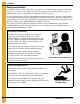
1. Safety Install and Operate Electrical Equipment Properly Electrical controls should be installed by a qualified electrician and must meet the standards set by the National Electrical Code and all local and state codes. Disconnect and lock out all power sources before installing wires/cables or servicing equipment.
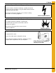
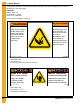
1. Safety Wear Protective Clothing Ear plugs or muffs should be worn at all times to protect ears from high noise levels. Wear close-fitting clothing and safety equipment appropriate to the job. Hearing Protection Eye Protection Remove all jewelry. Gloves Tie long hair up and back. Wear safety glasses at all times to protect eyes from debris. Wear gloves to protect your hands from sharp edges on plastic or steel parts. Wear steel-toed boots to help protect your feet from falling debris.
1. Safety General Safety Statement Our foremost concern is your safety and the safety of others associated with grain handling equipment. This manual is to help you understand safe operating procedures and some problems which may be encountered by the operator and other personnel. As owner and/or operator, you are responsible to know what requirements, hazards, and precautions exist and inform all personnel associated with the equipment or in the area. Safety precautions may be required from the personnel.
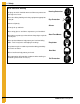
2. Safety Decals Safety decals should be read and understood by all people in the grain handling area. If a decal is damaged or is missing contact: GSI Decals 1004 E. Illinois St. Assumption, IL. 62510 Phone: 1-217-226-4421 A free replacement will be sent to you. WARNING Stay clear of rotating blade. Blade could start automatically. Can cause serious injury. Disconnect power before servicing. GSI Group Inc. 217-226-4421 AVERTISSEMENT Restez éloigné de la lame tournante.
2. Safety Decals DANGER DANGER HIGH VOLTAGE. HAUTE TENSION. Will cause injury or death. Causera des blessures ou la mort. Lockout power before servicing. Bloquez le courant avant de faire l’entretien. DC-1943 GSI Group 217-226-4421 Part #: DC-1943 Size: 5" x 3" Located on fan housing side above motor and located on outside of control box lid. DC-994 CIRCULATION D’AIR AIRFLOW AIRFLOW CIRCULATION D’AIR DC-1971 Part #: DC-1971 Size: 4-3/4" x 1-1/2" Located on painted inlet cone of fan housing.
2. Safety Decals NOTICE AVIS LIRE LE MANUEL DU PROPRIÉTAIRE AVANT DE FAIRE FONCTIONNER. Read owner’s manual before operating. FAIRE FONCTIONNER ĽUNITÉ DE MOTEUR MENSUELLEMENT ET CE PENDANT 20 MINUTES. CECI PERMET DE MAINTENIR UN BON FONCTIONNEMENT DES COMPOSANTS ET AUSSI D`ÉVITER UNE POSSIBILITÉ DE DÉFAILLANCE VENANT LE TEMPS DE LA RÉCOLTE. To maintain proper working components and avoid possible failure at harvest time, operate motor unit for 20 minutes each month.
2. Safety Decals Roof Damage Warning and Disclaimer The manufacturer does not warrant any roof damage caused by excessive vacuum or internal pressure from fans or other air moving systems. Adequate ventilation and/or “makeup air” devices should be provided for all powered air handling systems. The manufacturer does not recommend the use of downward flow systems (suction). Severe roof damage can result from any blockage of air passages.
3. Installation Pre-Installation Requirements Foundation Use the dimension illustration in the specifications section on Page 20 of this manual to determine the physical size of the fan to be installed. Use the dimensions shown to determine the position of the fan installation with respect to other equipment. For proper operation of the fan, the unit is to be mounted on a level pad. The fan should not be anchored to the pad, but it should be allowed to “float” on the pad.
3. Installation Fan Installation 1. Remove packaging materials and inspect fan for any shipping damages. Report these at once to the shipper. 2. Check all fasteners on the fan to make sure they are tight. (Fasteners may loosen during shipment.) Tighten any loose fasteners, check for proper clearance and retighten. 3. Check all electrical connections that may have loosened during shipment. 4. Rotate the fan wheel. Wheel should rotate freely and should not make contact with the housing sides or inlet cone.
3. Installation CAUTION The voltage between L1 and N must be 115 VAC. Any other voltage will cause damage to equipment. Check this voltage before starting unit. If voltage is not within 105 VAC-125 VAC, check for proper voltage on L2 or L3 and move to appropriate leg. If voltage is not acceptable, install a 1/4 KVA step-down transformer. NOTE: Grounded B and some open delta power supplies will require this transformer kit. Final Check Check to make sure all safety guards are in place and not damaged.
3. Installation Machine to Earth Ground It is very important that a machine to earth ground rod be installed at the fan. This is true even if there is a ground at the pole 15' away. This ground needs to be as close to the fan as possible, but no more than 8' away. The ground rod should be connected to the fan control panel with at least a #6 solid bare copper ground wire, or in accordance with local requirements. The machine to earth ground provides additional safety if there is a short.
4. Fan Specifications 1750 RPM Fan Electrical Specifications Fan Horsepower Phase 3 1 5 3 7-1/2 1 3 1 10 3 1 3 Volts 230 230 460 575 230 230 460 575 230 230 460 575 230 230 460 575 Full Load Current (Amps) * 17 9.6 4.8 3.9 28 15.2 7.6 6.
4. Fan Specifications 3500 RPM Fan Electrical Specifications Fan Horsepower Phase 3 5 1 3 7-1/2 1 3 1 10 3 1 3 Volts 230 230 460 575 230 230 460 575 230 230 460 575 230 230 460 575 Full Load Current (Amps) * 17 9.6 4.8 3.9 28 15.2 7.6 6.
4. Fan Specifications Fan Dimensions Figure 4A 1750 RPM Fan Housing Dimensions Fan CF-3 A 44 B C D E F 37.875 25.094 15.313 30.813 23.593 G 13.5 H I J K L M N 32.094 15.688 28.813 15.313 19.656 24.875 26.125 CF-5 48.563 42 27.719 17.063 34.688 27.25 CF-7.5 48.563 42 27.719 17.063 38.438 27.25 14.25 36.125 16.438 32.563 17.063 21.968 27.375 29.125 CF-10 53 45.938 30.125 18.406 38.625 29.875 17.438 40.094 19.781 35.844 18.406 24.656 30 31.75 CF-15 53 45.938 30.125 18.
4. Fan Specifications Discharge Bolt Pattern Dimensions Figure 4B 1750 RPM Discharge Dimensions Fan CF-3 A B C D E F G H I J 1.531 4.688 5.906 5.906 7.094 1.094 0.875 2.406 7.844 *** CF-5 1.813 5.125 8.438 8.438 5.218 0.875 0.75 2.75 8.031 *** CF-7.5 1.813 5.125 8.438 8.438 5.218 0.875 0.75 3.75 9.906 *** CF-10 1.594 3.5 11.5 11.5 3.344 0.813 0.688 3.75 9.594 10.563 CF-15 1.594 3.5 11.5 11.5 3.344 0.813 0.688 5.75 10.313 11.281 CF-20 1.
4. Fan Specifications Inlet Cone Dimensions Figure 4C Size Painted Part # A B C D Hole Size # of Holes 15 C-7743 18.625 4.000 10.375 9.875 0.688 8 18 C-7745 22.750 5.388 12.625 21.750 0.875 16 22 C-7747 27.125 6.750 15.625 26.125 0.875 16 24 C-7749 30.500 7.250 17.000 29.125 1.000 16 27 C-7751 33.125 8.000 18.813 31.750 1.000 16 30 C-7753 36.500 9.000 21.125 35.125 1.000 16 33 C-7754 38.750 10.000 23.063 38.376 1.
4. Fan Specifications Fan Wheel Dimensions Figure 4E Fan Model Wheel Assembly Part # * Size A B C 1750 RPM Fans CF-3 CH-6878 22 23.000 15.875 4.956 CF-5 C-956 24 25.250 17.188 5.938 CF-7.5 C-957 24 25.250 17.188 8.875 CF-10 C-8533 27 27.625 19.000 8.375 CF-15 C-960 27 27.625 19.000 9.750 CF-20 CH-2076 30 30.625 21.313 9.625 CF-25 C-2046 30 30.625 21.313 10.750 CF-30 C-7319 33 33.156 23.428 9.000 CF-40 C-7320 33 33.156 23.428 11.
4. Fan Specifications Fan Pad Location Fan pad should be perpendicular to bin wall. Fan discharge centerline should lie on bin centerline. Recommended thickness for pad is 4" minimum. Top surface of pad should be 2" below bin foundation. Fans with downwind heaters require fan pad to be 48" wide and add 33" onto length (D). IMPORTANT: Fan pad and fan must be level and smooth for proper operation. Vibration problems can result from improper fan leveling.
5. Operation After initial installation and also prior to using the unit each season, check the operation to ensure proper functioning, adjustment and reliability. Fan Start-Up 1. Make certain the unit is properly installed and connected, as described within the installation section on Page 14 of this manual. All air passage joints and seams must be well sealed. 2. With main power supply turned OFF, rotate the wheel by hand to make certain it turns freely without contacting the housing or inlet cone. 3.
5. Operation Grain Storage Average grain temperature should be above 35°F in the winter and below 65°F in the summer. Always try to keep the grain within 10°F-15°F of the average monthly outside temperature. This means grain may need to be aerated on warm days during the winter to stay above 35°F when freezing temperatures are predominate. During the summer it may be necessary to aerate the grain on cool nights, so the 65°F temperature is not exceeded during the hot days of summer.
6. User Servicing Instructions and Troubleshooting Always disconnect and lock out power before working on or around fan. DANGER Important Information Regarding Fuse Replacement This product employs overload protection (fuse). A blown fuse indicates an overload or short circuit situation. If the fuse blows, disconnect all power to the product. Replace the fuse as per the user servicing instructions (follow product marking for proper fuse rating) and check the product.
6. User Servicing Instructions and Troubleshooting Installation 1. Carefully clean motor shaft, key, bushing and bore of wheel. MAKE SURE MAIN POWER IS LOCKED OUT and that shaft and key are completely free of rust and burrs. DO NOT lubricate the bushing or cap screws. CHECK AND MAKE SURE ALL MOTOR MOUNT BOLTS ARE PROPERLY TIGHTENED. Before installing the wheel, check the following: a. All foreign material should be removed from the wheel. b.
6. User Servicing Instructions and Troubleshooting Taper-Lock Bushing Torque Requirements Browning Taper-Lock Bushing Bolt Tightening Torque Bushing Size Hex Bolt Size Torque (inch-lbs) P 5/16"-18 x 1-1/4" 192 Q 3/8"-16 x 1-1/2" 348 Fan Motor Removal and Installation In the event of motor failure, remove the motor, as described and take it to the nearest authorized service station. AUTHORIZED SERVICE STATIONS ARE THE ONLY PLACES THAT CAN PROVIDE MOTOR WARRANTY.
6. User Servicing Instructions and Troubleshooting Lubrication and Bearings Bearing grease will lose its lubricating ability over time, not suddenly. The lubricating ability of a grease (over time) depends primarily on the type of grease, the size of the bearing, the speed at which the bearing operates and the severity of the operating conditions. Good results can be obtained if the following recommendations are used in the maintenance program.
6. User Servicing Instructions and Troubleshooting Lubrication Intervals - Ball Bearing Motors Type of Annual Usage 1800 RPM - NEMA Frame Size 3600 RPM - NEMA Frame Size Up to 280 incl. Over 280 to 360 incl. Over 360 Up to 280 incl. Over 280 to 360 incl.
6.
7. Parts List 1. Main Assembly - 1750 RPM Fans - (See Page 34-38.) 2. Main Assembly - 3500 RPM Fans - (See Page 39-43.) 3. Main Assembly - Single Inlet Direct Drive Fan - (See Page 44.) 4. Main Assembly - Double Inlet Fan - (See Page 45.) 5. Internal Bearing Arch Assembly - Double Inlet Fan - (See Page 46.) 6. Motor Drives - Double Inlet Fan - (See Page 47.) 7. Shaft Coupling - (See Page 48.) 8. Small Control Panel 1 Phase 230 Volt (CPS-230-1) - (See Page 50-51.) 9.
7.
7. Parts List Main Assembly - 1750 RPM Fans (Continued) Model: CF-7.
7.
7.
7.
7.
7. Parts List Main Assembly - 3500 RPM Fans (Continued) Model: CHS-7.
7.
7.
7.
7. Parts List Main Assembly - Single Inlet Direct Drive Fan Main Assembly - Single Inlet Direct Drive Fan Parts List Ref # 44 Part # Description Qty Ref # Part # Description Bearing Mount Shaft Guard Qty 1 C-7752 Grill Guard: 30"/33" Painted 1 10 C-7736 2 2 C-7753 Inlet Cone: 30" Painted - 20 HP 1 11 HH-7041 Plug 2" Plastic Hole 1 2 C-7754 Inlet Cone: 33" Painted - 30, 40, 50 HP 1 12 C-7519 Leveling Leg 4 3 C-8071 Blade Assembly 30" 1750 - 20 HP D.D.S.I.
7. Parts List Main Assembly - Double Inlet Fan Main Assembly - Double Inlet Fan Parts List Ref # Part # Description Qty Ref # 1 12 C-8570 Blade Assembly D.I. 30 HP Standard 1 13 Blade Assembly D.I. 40 HP Standard 1 14 1 C-7752 Grill Guard: 30"/33" Painted 2 C-7040 2 C-7315 2 C-7044 Blade Assembly D.I. 50 HP Standard 1 Part # Description Qty Companion Flange Kit - C.F Fans 1 C-7519 Leveling Leg 4 C-8322 Leveling Leg Bracket - 0.
7. Parts List Internal Bearing Arch Assembly - Double Inlet Fan Internal Bearing Arch Assembly - Double Inlet Fan Parts List Ref # 1 2 3 4 A B C D E Part # C-7709 C-8446 C-8447 C-8395 Description Bearing Arch Weldment C.F D.I Internal Bearing Weld - 04 D.I C.F Internal Bearing Mount Plate Bearing - Griptight 211 2.
7. Parts List Motor Drives - Double Inlet Fan External Bearing Mount Assembly Ref # Part # Description Qty Ref # Part # Description Qty 1 3000-3 Motor 30 HP 3 PH 1800 RPM 1 11 C-8394 Square Key 1/2" x 3-1/4" 2 1 4000-3 Motor 40 HP 3 PH 1800 RPM 1 12 Reference Control Box Assembly 1 1 5000-3 Motor 50 HP 3 PH 1800 RPM 1 13 Reference Conduit Assembly 1 2 C-8403 D.I Motor Mount Top Plate 1 3 C-8404 D.
7.
NOTES PNEG-163-08 Centrifugal Fan 49
7.
7. Parts List Small Control Panel 1 Phase 230 Volt (CPS-230-1) Parts List Ref # Part # Description Qty 1 C-8707 Control Box Backing Plate - C-8705 1 2 E160-1137 Lug Ground, #TA-2 (CSA) 3 3 C-8718 Single Pole Midget Fuse Block 1 4 C-8719 Slow Blow 2A Midget Fuse 500 VAC, 10 KA I.R. 1 5 C-8715 1-1/2" x 13/32" Fuse Puller 1 6 C-8716 P.B.
7.
7. Parts List Small Control Panel 3 Phase 230 Volt (CPS-230-3) Parts List Ref # Part # Description Qty 1 C-8707 Control Box Backing Plate - C-8705 1 2 E160-1137 Lug Ground, #TA-2 (CSA) 3 3 C-8716 P.B. Switch Green FL, Red Ext w/ ISO Symbol IP66 NEMA 4 1 4 C-8718 Single Pole Midget Fuse Block 1 5 C-8719 Slow Blow 2A Midget Fuse 500 VAC, 10 KA I.R.
7.
7. Parts List Large Control Panel 3 Phase 230 Volt (CPL-230-3) Parts List Ref # Part # Description Qty 1 C-8708 Large Control Box Backing Plate 1 2 056-2072-9 Lug for 150A Contactor 3 3 056-2110-7 Contact, 2 N.O. Side Mount I 1 4 C-8716 P.B. Switch Green FL, Red Ext w/ ISO Symbol IP66 NEMA 4 1 5 C-8718 Single Pole Midget Fuse Block 1 6 C-8715 1-1/2" x 13/32" Fuse Puller 1 7 C-8719 Slow Blow 2A Midget Fuse 500 VAC, 10 KA I.R.
7.
7. Parts List Small Control Panel 3 Phase 380V, 460V and 575V (CPS-345-3) Parts List Ref # Model Part # Description Qty 1 C-8707 Control Box Backing Plate - C-8705 1 2 C-8715 1-1/2" x 13/32" Fuse Puller 3 3 C-8716 P.B. Switch Green FL, Red Ext w/ ISO Symbol IP66 NEMA 4 1 4 C-8719 Slow Blow 2A Midget Fuse 500 VAC, 10 KA I.R. 1 5 C-8720 Slow Blow Class CC Fuse ATQR8/10 2 6 E160-1137 Lug Ground, #TA-2 (CSA) 3 7 C-8717 Push Mount Cable Tie Assembly 10 8 056-2110-7 Contact 2 N.
7.
7. Parts List Large Control Panel 3 Phase 460V and 575V (CPL-345-3) Parts List Ref # Part # Description Qty 1 C-8708 Large Control Box Backing Plate 1 2 C-8716 P.B. Switch Green FL, Red Ext w/ ISO Symbol IP66 NEMA 4 1 3 C-8720 Slow Blow Class CC Fuse ATQR8/10 2 4 C-8719 Slow Blow 2A Midget Fuse 500 VAC, 10 KA I.R. 1 5 C-8715 1-1/2" x 13/32" Fuse Puller 3 6 056-2072-9 Lug for 150A Contactor 3 7 056-2110-7 Contact, 2 N.O.
7. Parts List Motor Conduit Assembly Fan Model CF-3 CF-5 CF-7.
7. Parts List Motor Conduit Assembly (Continued) Fan Model CHS-3 CHS-5 CHS-7.
7. Parts List Motor Conduit Assembly (Continued) Motor Conduit Assembly Fan Model Conduit Assembly 1P 230V 3P 230V 3P 460V CHS-3 C-8267 C-8265 C-8568 C-8568 CHS-5 C-8264 C-8265 C-8568 C-8568 CHS-7.
7. Parts List Motor Conduit Assembly (Continued) C-8310 - Conduit Assembly 1-1/2" x 60" Str/Elbow 6 Ref # Part # Description 1 006-1092-3 Connector Sealtite 90° 1-1/2" 2 C-7213 3 C-8311 - Conduit Assembly 2" x 60" Str/Elbow 1 Gauge Qty U/M Ref # 1 EA 1 C-7218-A Tape 3/4 x 66' 3M Plastic 0.2727 RL 2 C-7214 Tape Rubber Wrap 3/4 x 30' 0.
7. Parts List Motor Conduit Assembly (Continued) Motor Conduit Assembly Fan Model Conduit Assembly 1P 230V 3P 230V CF-30D - C-8439 C-8440 CF-40D - C-8450 C-8438 CF-50D - C-8450 C-8436 C-8572 - Conduit Assembly 1" x 60" Str/Elbow 12 Gauge Ref # Part # Description Qty C-8568 - Conduit Assembly 3/4" x 36" Str/Elbow 1 U/M Ref # Part # Description 1 C-7213 Tape 3/4 x 66' 3M Plastic 0.1818 RL 1 067-1044-6 Connector Sealtite STR 3/4" 2 C-7214 Tape Rubber Wrap 3/4 x 30' 0.
7. Parts List Motor Conduit Assembly (Continued) C-8450 - GRP-DI Conduit 3P230 #1 2 x 48 Ref # Part # Description C-8440 - GRP-DI Conduit 3P460 #6 1-1/2 x 48 Qty U/M Ref # Part # Description Qty U/M 1 EA 1 C-7218-A GRP-Splice Bolt 1H3 Blackburn 3 EA 1 006-1092-3 Connector Sealtite 90° 1-1/2" 2 E305-0188 WR 60" (10 Green/Yellow) 1/4/Ring Term 1 EA 2 C-7213 Tape 3/4 x 66' 3M plastic 0.2727 RL 3 GT3-0274 Sealtite 2" 4 FT 3 C-7214 Tape Rubber Wrap 3/4 x 30' 0.
8.
8.
8.
8. Schematics/Wiring Diagrams Wiring Diagram - CF-10-1C and CHS-10-1C Motor Part # Capacitor Part # Capacitor Type MFD Voltage Qty CHS-10-1 Capacitor Specifications FH-7000 Electrolytic 216 250 3 CH-6897 Oil 30 370 2 FH-5480 CF-7.
8.
8. Schematics/Wiring Diagrams Wiring Diagram - CF-5-1C, CF-7.5-1C, CHS-5-1C and CHS-7.
8.
8. Schematics/Wiring Diagrams Wiring Diagram - 230 Volt 3 Phase NOTE: Refer to Chart below to determine which connection diagram to use. Fan Model Motor Connection Diagram Fan Model Motor Connection Diagram CF-3 CD0005 CHS-3 CD0005 CF-5 CD0005 CHS-5 CD0005 CF-7.5 CD0005 CHS-7.
8.
8.
9. Appendix A Double Inlet Fans NOTE: Refer to supplements provided by component manufacturers for installation and maintenance of the double inlet fan bearings and shaft coupling.
10. Warranty GSI Group, LLC Limited Warranty The GSI Group, LLC (“GSI”) warrants products which it manufactures to be free of defects in materials and workmanship under normal usage and conditions for a period of 12 months after sale to the original end-user or if a foreign sale, 14 months from arrival at port of discharge, whichever is earlier.
This equipment shall be installed in accordance with the current installation codes and applicable regulations which should be carefully followed in all cases. Authorities having jurisdiction should be consulted before installations are made. GSI Group 1004 E. Illinois St. Assumption, IL 62510-0020 Phone: 1-217-226-4421 Fax: 1-217-226-4420 www.gsiag.